LET'S TALK ABOUT 3D SCANNING |

|
In the ever-evolving world of watersports, efoiling has taken the spotlight with its thrilling combination of surfing and flying above water. Efoil boards, propelled by electric motors, offer an exhilarating experience, and at the heart of their performance lies the efoil wing. However, this industry is young and manufacturers struggle to survive such as FOIL Inc (getfoil.com) as there is not enough demand out there leaving enthusiasts in a lurch when their favorite wing model is no longer available to purchase and the original designs may be lost. Fortunately, 3D scanning and reverse engineering offer a lifeline for reviving these designs. In this blog post, we'll explore how you can use 3D scanning technology to bring an out-of-production foil wing back to life. Importance of the Efoil Wing The efoil wing is crucial for the lift and stability of the board, directly affecting the rider's experience. Each wing model has its unique design that caters to different riding styles, water conditions, and skill levels. When a beloved wing is no longer produced, finding a suitable replacement can be challenging, making reverse engineering an appealing solution. We have 3D scanned the efoil wing 200 of the FOIL series using the EinScan Pro HD with high accuracy as the initial step to enable full reverse engineering and manufacturing. PART I: 3D SCANNNING TO CAPTURE THE ACCURATE SIZE AND CURVATURE Step 1: Preparing for 3D Scanning Before diving into the scanning process, you'll need the right tools and a suitable environment. Here is what we used.
 EinScan Pro HD and the Wing prepared with markers
Step 2: 3D Scanning the Efoil Wing
Step 3: Post Processing
 Aligning the Front & Back Scans  Post-Processed 3D Scan Mesh File Here is the STL file so you can further reverse engineer and manufacture via 3D printing!
PART II: REVERSE ENGINEERING
PART III: MANUFACTURING Once satisfied with the redesigned model, it's time to manufacture the wing.
CONCLUSION 3D scanning and reverse engineering provide a powerful combination for resurrecting discontinued efoil wings. By capturing the precise geometry of a classic wing and using modern tools to refine and replicate its design, enthusiasts can continue to enjoy their favorite efoil experiences. Whether you're an efoil aficionado or a watersports innovator, this technology opens up a world of possibilities for preserving and enhancing the sport. So, don't despair about FOIL Inc going bust, let technology breathe new life into it! Growshapes the official U.S. distributor of Shining 3D EinScan 3D scanners. We now carry the eviXscan 3D scanner from Evatronix as well!
See the innovators on Growshapes’ social media channels to get the latest expert news on innovation in 3D digitization, then share your thoughts and join the conversation about 3D digital innovation with #digitize3D
0 Comments
In today's rapidly evolving technological landscape, 3D scanning has emerged as a powerful tool across various industries, from manufacturing, quality control, and design to healthcare and entertainment. If you're considering incorporating a 3D scanner into your workflow, the decision to buy is a capital investment that needs to be made carefully with confusing choices, limited budgets, and not the best option. One good option before making a significant investment is to rent a 3D scanner. Growshapes offers a 3D scanner rental program for select EinScan 3D scanner models at an affordable price with flexible rental periods. Here are 5 reasons why renting a 3D scanner can be highly advantageous before you commit to a purchase. 1. Cost-Effective Trial Run Purchasing a 3D scanner is a considerable financial commitment, with prices ranging from a few thousand to tens of thousands of dollars, depending on if you want a super high accuracy with precise measurements for your reverse engineering project or you want a high definition model with accurate measurements for historical preservation. Renting allows you to experience the technology firsthand without the hefty upfront cost and figure. The 3D scan output files are ASC, P3, STL, PLY, OBJ, and 3MF. With the rental program, you can evaluate which 3D scanner model is the most effective solution with the best scanning experience for you and if it is worth the investment. 2. Access to the Latest Technology The world of 3D scanning is continuously evolving, with models and technologies being released frequently. Renting a 3D scanner gives you access to the latest advancements without the need to constantly upgrade your equipment and try it at your project site and share the experience with your team members. This ensures you are always working with the most current and efficient technology available. 3. Hands-On Learning Experience Renting a 3D scanner provides a hands-on learning experience, allowing you to familiarize yourself with its operation, capabilities, and limitations. This practical experience can be invaluable in understanding how the scanner can be integrated into your specific applications and workflows. You can get hands-on experience on the point cloud processing software and the mesh generation workflow and export it to the software of your choice for further processing. The 3D scan output files are ASC, P3, STL, PLY, OBJ, and 3MF. 4. Flexibility and Convenience Different projects may require different types of 3D scanners. By renting, you can select the most suitable scanner for your specific project. This flexibility ensures optimal performance and results for varying scanning needs, from small objects to large objects without having to purchase and then return. It's a win-win situation for both the buyer and the seller. 5. Evaluate Performance and Compatibility Every 3D scanner has unique features and specifications. Renting allows you to test the scanner’s performance in real-world conditions and ensure it is compatible with your existing software and hardware. This trial period helps identify any potential issues or limitations, allowing you to make an informed purchasing decision. Conclusion Renting a 3D scanner before purchasing one offers a range of benefits that can help you make a more informed decision and decide if it is a continuing need. It provides a cost-effective way to explore the technology, access the latest trends, gain hands-on experience, and ensure compatibility with your existing systems. Additionally, the flexibility and support that come with renting make it an attractive option. By renting first, you can confidently determine whether investing in a 3D scanner is the right choice for your business or project. Equipment rental options start from a minimum of 1 week. Our customers who rented liked the ease of renting with quick responses from us, the ease of use of the 3D scanner and the support we provided when they got stuck in the 3D scanning process, and so far only 1 of our customers did not buy the 3D scanner as they didn't couldn't find a long-term use of the rented scanner. Click on the button below so our customer service team can get back to you with further details such as price and the best option to meet your specific needs. Growshapes the official U.S. distributor of Shining 3D EinScan 3D scanners. We now carry the eviXscan 3D scanner from Evatronix as well!
See the innovators on Growshapes’ social media channels to get the latest expert news on innovation in 3D digitization, then share your thoughts and join the conversation about 3D digital innovation with #digitize3D At the heart of every EinScan 3D scanner by Shining 3D lies cutting-edge technology designed that has been developed over 20 years to deliver exceptional precision and accuracy. Utilizing advanced structured light, invisible infrared light, or blue laser light sources for the 3D scanning depending on the model, EinScan scanners can capture intricate details in high resolution at sub-millimeter volumetric accuracy. This high accuracy is crucial for industries where exact measurements and detailed geometries are paramount, such as aerospace, automotive design, and medical device manufacturing. Exceptional Versatility in Different Scan Modes EinScan scanners offer versatile scanning modes to accommodate a wide range of object sizes and applications capturing the full geometry of objects:
User-Friendly Workflow Ease of use is a hallmark of EinScan scanners, making them accessible to both novice users and seasoned professionals alike. Intuitive software interfaces guide users through the scanning process, from setup to post-processing:
Applications Across Industries The versatility of EinScan scanners extends across diverse industries, driving innovation and efficiency in industrial applications to art and design offering you a professional experience:
Future-Proof Investment Investing in an EinScan 3D scanner is not just about acquiring cutting-edge technology—it's about future-proofing your capabilities and staying ahead in an increasingly competitive market. With continuous advancements in software, the updates come automatically with the purchase of the 3D scanner thus ensuring compatibility with emerging technologies, EinScan scanners ensure that your investment remains valuable and for years to come. Conclusion Whether you're looking to streamline manufacturing processes, innovate in design, or explore new frontiers in research and education, an EinScan 3D scanner empowers you to transform concepts into reality with unparalleled precision and efficiency. Our customer service team will help you choose the right model for your specific project. By choosing an EinScan scanner, you're not only investing in state-of-the-art technology but also embracing a tool that enhances creativity, accelerates workflows, and unlocks limitless possibilities in the world of 3D scanning and modeling. Embrace innovation. Choose EinScan with Growshapes. Unlock the power of precision 3D scanning today. Growshapes the official U.S. distributor of Shining 3D EinScan 3D scanners. We now carry the eviXscan 3D scanner from Evatronix as well!
See the innovators on Growshapes’ social media channels to get the latest expert news on innovation in 3D digitization, then share your thoughts and join the conversation about 3D digital innovation with #digitize3D In the realm of 3D scanning and modeling, various file export formats serve specific purposes, each type of file with its characteristics and applications. Whether you're involved in digital manufacturing, use 3D scanning to scan a physical part as a reverse engineering method for rapid prototyping, or want to create a digital version of a physical product for your digital animation, choosing the correct file type is crucial for ensuring compatibility and maintaining the integrity of your 3D surface models. In this blog post, we'll explore several common 3D scanner file formats that can be produced after the 3D scanning process. Types of output data format are ASC, P3, STL, PLY, OBJ, and 3MF, providing insights into what they are and how they are typically used. 1. ASC File (ASCII Point Cloud) Description: ASC files, also known as ASCII Point Cloud files, are plain text files that store 3D point cloud data. Each line in the file represents a point in 3D space, defined by its X, Y, and Z coordinates storing the position information of each point. Optionally, additional data such as color information (RGB values) or intensity may be included for each point. Purpose: ASC files are often used to store point cloud data captured from 3D scanning devices. They provide straightforward raw scan data for storing large sets of point clouds, which can then be processed for various applications such as reverse engineering, metrology, and digital preservation. 2. P3 File (ASCII Polygon File) File Description: P3 files are ASCII-based polygon mesh models that describe 3D geometry using vertex, edge, and polygon definitions. Each line in the file typically represents a vertex or polygon face, with additional information such as vertex normals and texture coordinates if applicable. Purpose: P3 files are commonly used for representing 3D polygonal meshes, making the final polygon file suitable for applications such as computer-aided design (CAD), visualization, and digital content creation (DCC) for animation and gaming. 3. STL File (Stereolithography) Description: STL files are one of the most widely used surface model file formats for 3D printing and the best option and best for exporting to CAD applications. They represent 3D surfaces as a collection of interconnected triangles (mesh data). STL files can be either ASCII or binary, with binary being more common due to a smaller file size. Purpose: The STL file format is ideal for 3D printing as it describes the surface geometry of an object using triangular facets. STL format is the most common file type of exported files into CAD software or reverse engineering software to create a solid model and add parametric features for reverse engineering, prototyping, and manufacturing, providing a universal format for exchanging 3D model data. 4. PLY File (Polygon File Format) Description: PLY files are flexible file formats that support a variety of properties for each vertex, such as color, transparency, and surface normals. They can store both ASCII and binary data, making them versatile for different applications. Purpose: PLY files are used in 3D scanning, computer graphics, and computational geometry. They are suitable for capturing detailed surface model information and are often used in applications requiring high-resolution representations of 3D objects. 5. OBJ File (Wavefront OBJ) Description: OBJ files are widely used for storing geometric data, including vertex positions, texture coordinates, vertex normals, and material definitions. They are ASCII-based and support basic geometric shapes as well as complex polygonal meshes. Purpose: OBJ files are popular in 3D modeling and rendering software, including animation and gaming. They are versatile for exchanging 3D models between different software packages and are supported by most CAD files and 3D graphics programs. 6. 3MF File (3D Manufacturing Format) Description: 3MF files are a modern file format designed specifically for additive manufacturing (3D printing). They can store a wide range of data including geometry, materials, textures, colors, and metadata in a single file. Purpose: 3MF files streamline the workflow from design to manufacturing by encapsulating all necessary information within a single file. They support advanced features such as lattice structures and multiple materials, promoting interoperability and efficiency in 3D printing workflows. Conclusion Choosing the right 3D scan file format for your new project depends on your specific application and workflow requirements. Whether you're capturing point cloud data from a 3D scanner, preparing models for 3D printing, or creating digital content for animation, understanding the characteristics and purposes of each file type is essential for achieving optimal results. By leveraging the capabilities of ASC, P3, STL, PLY, OBJ, and 3MF files, you can implement best practices while effectively managing and exchanging 3D data files across different platforms and industries, driving innovation and creativity in the world of 3D technology. Growshapes the official U.S. distributor of Shining 3D EinScan 3D scanners. We now carry the eviXscan 3D scanner from Evatronix as well!
See the innovators on Growshapes’ social media channels to get the latest expert news on innovation in 3D digitization, then share your thoughts and join the conversation about 3D digital innovation with #digitize3D Tools: Did you know custom car mats can improve not only the aesthetics but also the functionality of your car through improved protection? Now there is a way to create custom car mats using a 3D laser scanner without having to go through the original equipment manufacturers or an auto repair shop. An industrial designer can further help to get creative and design something the car owner wants as well! Here is a step-by-step guide to creating custom car mats using laser scanning technology. Perfect fitting custom mats that give complete coverage using laser scanning technology! Step 1: Laser Scanning with EinScan HX Scan the foot mat area of the car with the EinScan HX 3D scanner in laser scanner mode. Measuring interior surfaces is the main challenge with tape measures. A 3D scanner can quickly capture detailed data of the foot mat area with high accuracy in a digital format that can be exported to another software. Step 2: Importing 3D Data and Cutting the Mesh Once the scanning process is complete, you can export that data into Wrapstyler software. The Wrapstyler software supports OBJ and STL file formats. It is recommended to export the OBJ format is recommended as it can capture textures, which can be used to guide plane-cutting positions in specific cases. Wrapstyler’s interface is simple and intuitive, with a 3D view on the left and a 2D view on the right. Utilize Wrapstyler’s powerful tools to cut and shape the 3D mesh data according to your desired design. This step allows for creating intricate patterns and customized shapes that perfectly fit the foot mat area. Step 3: Flatten the 3D Scan to 2D Patterns The software intelligently flattens the 3D shapes into precise 2D patterns, providing a clear blueprint for the next steps to design the best floor mats Step 4: Deformations Before proceeding with the actual cutting process, Wrapstyler enables you to inspect the fit between the 2D patterns and the foot mat area. Detect and address any deformations to avoid material wastage and ensure a perfect match between the design and the car interior. Step 5: Add Seam Allowance Add necessary seam allowances. This step ensures a smooth transition from the 2D patterns to the final product so it can be sewn correctly. Step 6: Drawing and Cutting by Machine Prepare for production of the car mats by exporting the finalized 2D patterns. The drawings can be directly used for machine cutting, ensuring precision and efficiency in the manufacturing process. Step 7: Sewing The last thing that needs to be done is to sew the cut patterns together. The accurately tailored car mats will fit perfectly, enhancing not only aesthetics but also functionality. This step-by-step guide demonstrates how the EinScan 3D scanner and Wrapstyler 3D to 2D flattening software can deliver a precise, efficient process for producing customized car mats. Click on the video below for the highlights. If you want to see the full process, check out the check out the full webinar. Growshapes the official U.S. distributor of Shining 3D EinScan 3D scanners. We now carry the eviXscan 3D scanner from Evatronix as well!
See the innovators on Growshapes’ social media channels to get the latest expert news on innovation in 3D digitization, then share your thoughts and join the conversation about 3D digital innovation with #digitize3D Did you know 3D scanning can help you in immensely in improving the workflow in creating various prosthetics? See below how 3D scanning will improve the fit for different parts of the body. 1. Limb Prosthetics
2. Cranial and Maxillofacial Prosthetics
3. Orthopedic Prosthetics
4. Digital Prosthetics and Bionics
5. Aesthetic Prosthetics
6. Sports and Specialty Prosthetics
7. Pediatric Prosthetics
By leveraging 3D scanning technology, the prosthetics industry can provide devices that are not only more effective and comfortable but also more accessible to a wider range of patients. This technology's ability to create highly personalized solutions is a game-changer, significantly improving the quality of life for individuals requiring prosthetic devices. Interested? Check out the below 3D scanner for best results! 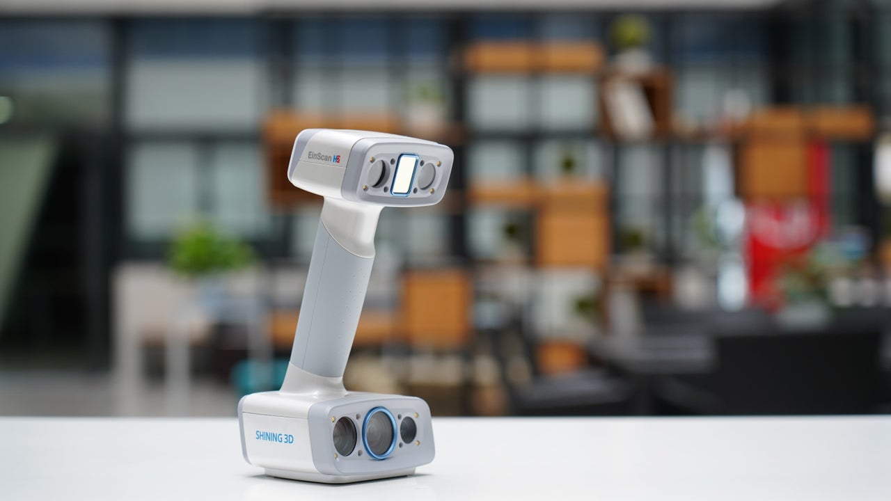 EinScan H2Growshapes the official U.S. distributor of Shining 3D EinScan 3D scanners. We now carry the eviXscan 3D scanner from Evatronix as well!
See the innovators on Growshapes’ social media channels to get the latest expert news on innovation in 3D digitization, then share your thoughts and join the conversation about 3D digital innovation with #digitize3D The new EXScan Pro V4.0 for the EinScan Pro series 3D scanners is a game-changer, delivering substantial improvements and innovative features to elevate your 3D scanning experience. From background segmentation to real-time marker recognition, automatic plane segmentation, and marker/point cloud editing, every feature is crafted to enhance precision and efficiency. The upgraded post-processing and measurement features, coupled with a user-friendly interface and additional functionalities, underscore our commitment to providing a seamless and enriched scanning experience for EinScan users. Watch the video to find out more! New Features for Fixed Scan Mode
New Features for Handheld Scan Mode
Upgraded Post Processing Features
Integration Upgrades
Growshapes the official U.S. distributor of Shining 3D EinScan 3D scanners. We now carry the eviXscan 3D scanner from Evatronix as well! See the innovators on Growshapes’ social media channels to get the latest expert news on innovation in 3D digitization, then share your thoughts and join the conversation about 3D digital innovation with #digitize3D 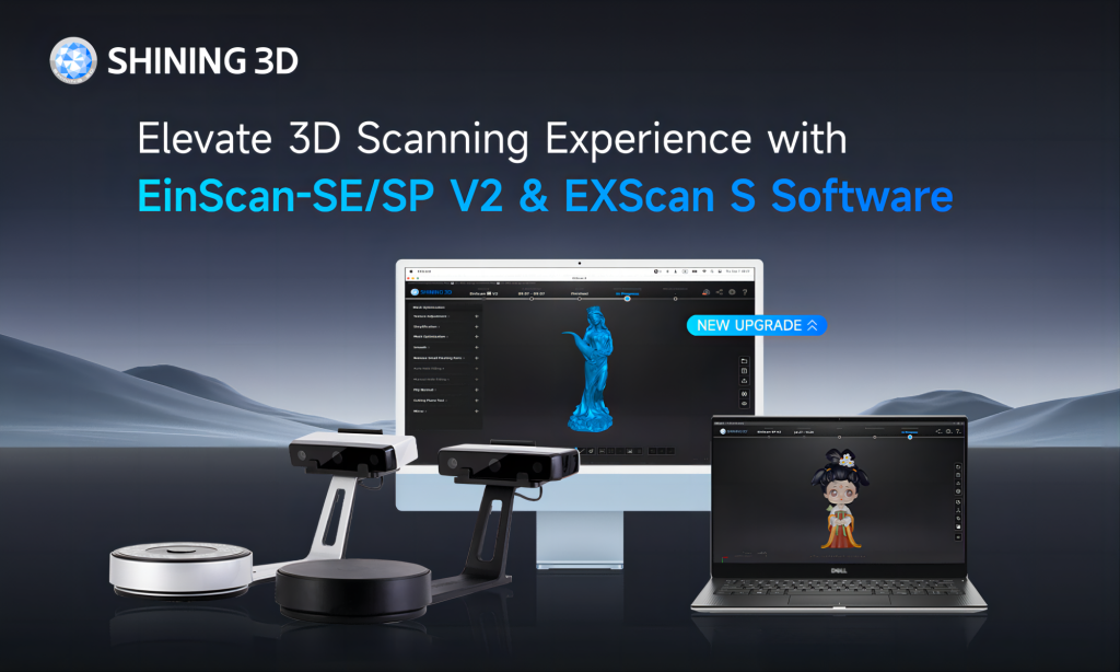 EinScan-SE/SP V2 offers enhanced user experience compared to its predecessors and what's more now it's compatible with macOS! The 3D scanning world has been predominantly Windows compatible, but now you have the option to use with your macOS. Enhnaced 3D scanner features:
macOS compatible EXSCAN S software offers the following features.
Growshapes the official U.S. distributor of Shining 3D EinScan 3D scanners. We now carry the eviXscan 3D scanner from Evatronix as well!
See the innovators on Growshapes’ social media channels to get the latest expert news on innovation in 3D digitization, then share your thoughts and join the conversation about 3D digital innovation with #digitize3D Have you ever wondered why your 3D scanner won’t capture the surface of certain objects? Or have you become frustrated by getting an incomplete 3D scan and scratching your head trying to figure out what you did wrong? Various 3D scanning technologies exist, i.e. structured light scanners, laser scanners, and photogrammetry, yet all have challenges due to the limitations of physics such as light passing through transparent objects. The surface of the object can make 3D scanning challenging. The below objects are usually challenging to 3D scan.
1. Highly-detailed objects When capturing highly detailed objects, it is essential to ensure that the 3D scanning parameters are adjusted to capture sharp edges and intricate details accurately for the best results. The default scan parameters may not always capture these elements with sufficient detail and high precision. However, by customizing the settings, you can obtain an accurate 3D model that faithfully represents the object without losing any important details. One crucial setting to adjust is the point distance, which determines the resolution of the scan. By selecting a smaller point distance, you can achieve a higher resolution and capture finer details even for medium-sized objects. The EinScan Pro Series multifunctional 3D scanner is an excellent choice for scanning detailed objects, offering an adjustable resolution of up to 0.2mm. With this scanner, you can reproduce intricate details with highest accuracy, ensuring a high level of precision in your 3D models captured as a .stl file. Furthermore, the EinScan Pro Series provides efficient 3D scanning capabilities and a user-friendly experience, making it an ideal solution for capturing highly detailed objects with ease. 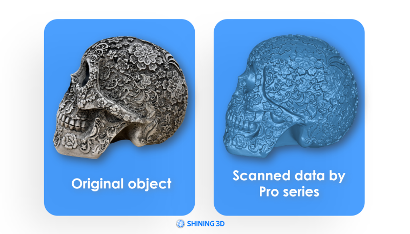 If you require a 3D scanner capable of capturing intricate details, a desktop 3D scanner would be a suitable choice. Among the recommended options are the EinScan SE, EinScan SP, Transcan C, EinScan Pro Series set up on a tripod. The Transcan C, in particular, offers an impressive resolution of up to 0.035mm, ensuring excellent detail reproduction. It's important to note that the highest resolution scans result in denser point clouds, which means more data and larger file sizes. Additionally, the software will take longer to process a greater amount of data. Therefore, it is generally recommended to use fine resolution settings for small or medium-sized objects. Scanning larger objects with a desktop 3D scanner or tripod setup can be time-consuming and labor-intensive as well. Before choosing a scanning method, consider the size of your objects. Finding the right balance between scan quality and efficiency is crucial. Assess the trade-off between the level of detail required and the time and resources available for scanning larger objects. By carefully considering these factors, you can select the most appropriate scanning method for your specific needs. 2. Dark surfaces If you've encountered difficulties in 3D scanning dark objects, you're not alone. Dark surfaces pose a common challenge in the 3D scanning process due to their high light absorption. Just like wearing a dark-colored shirt under the sun, dark colors absorb more light, which makes it difficult for 3D scanners to accurately capture their surface details. To overcome this challenge, there are a few techniques you can employ. One approach is to attach adhesive markers or targets to the object. These markers act as reference points that assist the 3D scanner in tracking and aligning the scan data. Another option is to apply white powder as simple as baby powder or Aesub Blue 3d scanning spray to the dark surface, which helps enhance the reflection of light and improve scan results. However, these methods can be time-consuming, and messy, and may not be suitable for delicate objects. Fortunately, not all light sources are created equal, and certain 3D scanners offer better performance when scanning dark surfaces. A more powerful laser and the use of blue light can be effective in capturing dark objects. Blue light has a narrower wavelength compared to white or red light, allowing for better resolution and detail capture. The EinScan HX is equipped with powerful laser lines and blue LED light in its fast mode. This combination of technologies enables efficient scanning of dark surfaces without the need for markers or white spray. In just minutes, the EinScan HX can produce high-quality scans, even for objects as challenging as a black lion sculpture. By utilizing advanced 3D scanning technologies specifically designed for dark surfaces, you can achieve accurate and detailed scans without the additional steps of applying markers or powder. 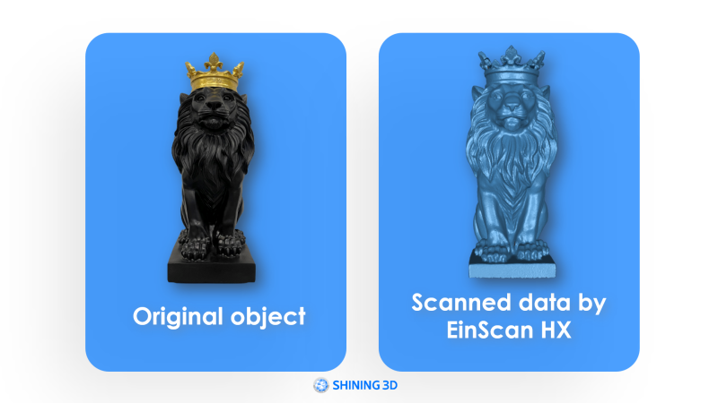 3. Reflective or shiny surfaces Scanning objects with siny and reflective surfaces present another common challenge in 3D scanning. While dark surfaces absorb light, shiny surfaces, such as mirrors or shiny metal parts, disperse and reflect light in various directions, making it difficult for 3D scanners to accurately capture the object's details. Remember how 3D scanners work. 3D scanners project light onto objects, and measure how the light is returned or deformed, but reflections make it impossible to read. In industries like machinery or automotive, shiny and metallic parts are often scanned, necessitating specific techniques to overcome this challenge. Markers and the power of the light source play crucial roles in scanning shiny surfaces. A more powerful and high-quality light source significantly improves a 3D scanner's ability to capture data from shiny objects. In some cases, especially with medium and large-sized objects, markers may be necessary to ensure excellent scanning results. Using magnet markers can provide a quick, easy, and non-destructive removal solution as well. The EinScan HX, equipped with a powerful blue laser light source and marker recognition capability, is designed to address this 3D scanning challenge. Among all the EinScan Series 3D scanners, it is the only one capable of effectively capturing shiny objects. Its advanced features enable successful scanning of metallic surfaces, as demonstrated in the example below. 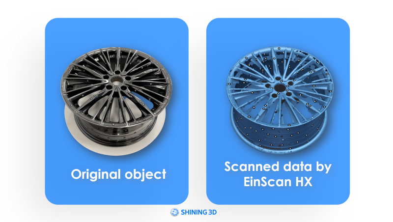 4. Colorful object When scanning brightly colored objects, it is crucial to ensure accurate representation of the object's color information in the generated data for good results. This heavily relies on the pixel count or digital resolution of the texture camera used. Pixel count is typically measured in megapixels (MP), where one MP equals one thousand pixels. Insufficient camera resolution can result in color distortion and loss of detail. The good news is that all EinScan 3D scanners can capture texture data. The EinScan H and HX models come equipped with built-in color cameras, while the Pro Series offers color capture functionality through an optional color pack add-on. Different 3D scanner models offer varying camera resolutions to accommodate different budgets and specific use cases. For those seeking the highest level of color detail, the Transcan C 3D scanner is the ideal choice. It features an exclusive 12-megapixel texture camera, offering superior color detail with its higher pixel count. With the Transcan C, you can expect to capture the finest color details and achieve excellent color accuracy in your 3D scans. 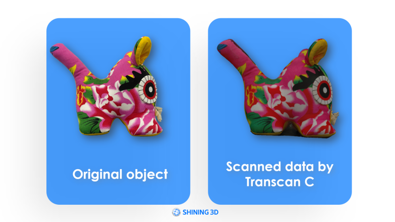 5. Scanning humans When it comes to 3D scanning the human body, there are three key challenges that need to be considered: (1) maintaining stillness, (2) avoiding direct light in the eyes, and (3) successfully capturing fine details such as hair. Firstly, it is crucial for the subject to remain as still as possible during the scanning process. Even the slightest movement, such as blinking or shivering, can introduce inaccuracies in the final 3D model. Secondly, some scanners utilize intense LED lights that can be uncomfortable or temporarily impair vision if directly exposed to the eyes. This can cause discomfort and hinder the scanning experience. Lastly, capturing the intricate details of human hair presents a challenge due to its thin nature and the potential for it to blend together or appear less defined in the scan. Fortunately, specialized 3D scanners have been developed to address these specific challenges. The EinScan H2 and Einstar are excellent examples. These scanners incorporate "non-rigid" algorithms in their software that automatically compensate for slight body movements, reducing the impact of any minor shifts during scanning. Additionally, they utilize infrared rays instead of LED lights or lasers, eliminating any discomfort or vision impairment. Infrared technology proves effective at capturing both dark and light-colored hair, ensuring accurate representation of fine hair details in the resulting 3D scans. When it comes to body 3D scanning, the EinScan H and Einstar, along with their dedicated software, serve as efficient and reliable allies, helping overcome the challenges associated with scanning the human body. As you can see below, EinScan H will give you much more detail than the Einstar. 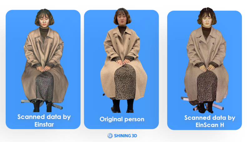 Conclusion Despite the challenges posed by certain surfaces, to get the final result you want is possible by employing the right combination of hardware and software solutions. The EinScan series offers a wide range of 3D scanners designed to accommodate various situations and budgets. Each scanner within the EinScan lineup possesses unique features and specifications, making them suitable for different users and applications. Whether you're scanning complex surfaces, intricate details, or specific objects, there is an EinScan 3D scanner that fits your requirements. If you find yourself uncertain about scanning a particular surface or need guidance in selecting the most suitable scanning solution, don't hesitate to reach out to Growshapes! Our team is available to provide assistance and support to ensure you choose the optimal scanner for your needs. For those interested in delving deeper into the world of 3D scanning, we invite you to explore our webinar titled "Things You Should Know Before Buying a 3D Scanner." This webinar offers valuable insights and knowledge to help you make informed decisions. You can also refer to this blog "Which handheld 3D scanner is best for me?" We are committed to providing you with the necessary resources and support to ensure your 3D scanning endeavors are successful and tailored to your specific needs. To try before you buy, contact us too! Growshapes the official U.S. distributor of Shining 3D EinScan 3D scanners. We now carry the eviXscan 3D scanner from Evatronix as well!
See the innovators on Growshapes’ social media channels to get the latest expert news on innovation in 3D digitization, then share your thoughts and join the conversation about 3D digital innovation with #digitize3D Every once in a while, it’s important to revisit the basics to understand how 3D scanners work. In this blog post, we’ll cover the Field of View (FOV) of a 3D scanner and how it affects the 3D scan results. The key takeaway is that different 3D scanners have different FOVs, and choosing the right model is crucial to getting the right output depending on the size of the object you want to 3D scan. What is Field of View (FOV)?Like how humans can see a certain range (you can't see behind you) at a given moment, different 3D scanners have a different viewable area at one time from a specific distance. The larger the FOV, the larger area the 3D scanner can 'see' thus capture at once. With the EinScan 3D scammer models, there is a variety of scanning range among different 3D scanner models that scan something as small as a coin to something as large as a car. Therefore, it is important to understand what you are scanning and what FOV is most suitable to capture the details of the object. 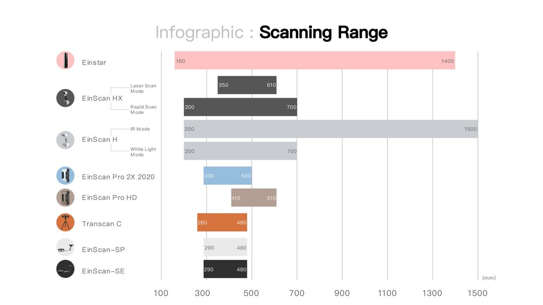 FOV of Different EinScan 3D Scanner Models The FOV of a 3D scanner can determine which model is best suited to 3D scan your object depending on its size. Choosing the right field of view is about finding the right balance between capturing enough detail of the object you want to scan and appropriate coverage for each scan. This balance is important so you can achieve a smoother scanning experience, complete scans in a shorter amount of time as well as reduce computer crashes that happen when the software is overloaded. 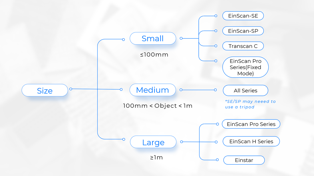 Target Object Size and Suitable 3D Scanner Models
|
||||||||||||||||||||||
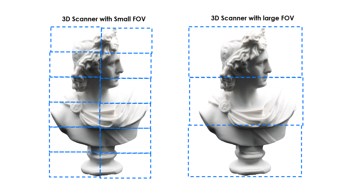 | What happens when you use a 3D scanner with a small FOV to scan large objects? When you scan a large object with a 3D scanner optimized for scanning small objects, you will have to do more scans to reconstruct a complete 3D digital model than you would with a scanner with a large FOV. Look at the theoretical diagram on the left. If you have a large FOV, you only need 3 scans but with a small FOV you need 12 scans. In reality there are overlaps so this is just an illustration. |
|
Now let's see what happens when I use a 3D scanner with a large FOV to scan small objects.
When you are scanning small objects with complex details and texture information, the 3D scanner with a large FOV will not be able to see the fine geometric details. |
Vertical Divider

|
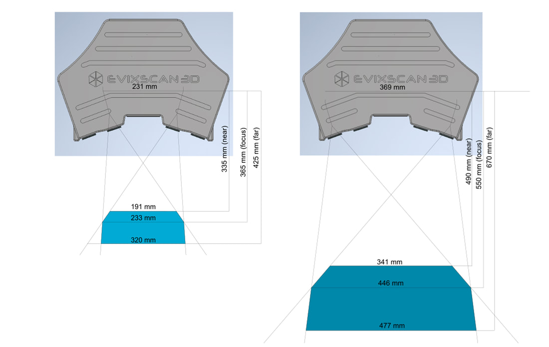
Some scanners have dual FOV like the Transcan C and the eviXscan 3D Quadro+ so it can scan small and medium size objects. On the TranScan C, you can slide the cameras out to increase the FOV, while on eviScan Quadro there are 4 cameras installed - the inner cameras and the outer cameras.

Transcan C
|
Vertical Divider
eviXscan 3D Quadro+
|
It really depends on the simplicity and versatility you require for the project. Naturally, having multiple FOV is a bit more complex due to having varying settings.
Now let's dig a little deeper and look at the difference in FOV of Einscan Pro HD vs. Einscan Pro 2X 2020.
Now let's dig a little deeper and look at the difference in FOV of Einscan Pro HD vs. Einscan Pro 2X 2020.
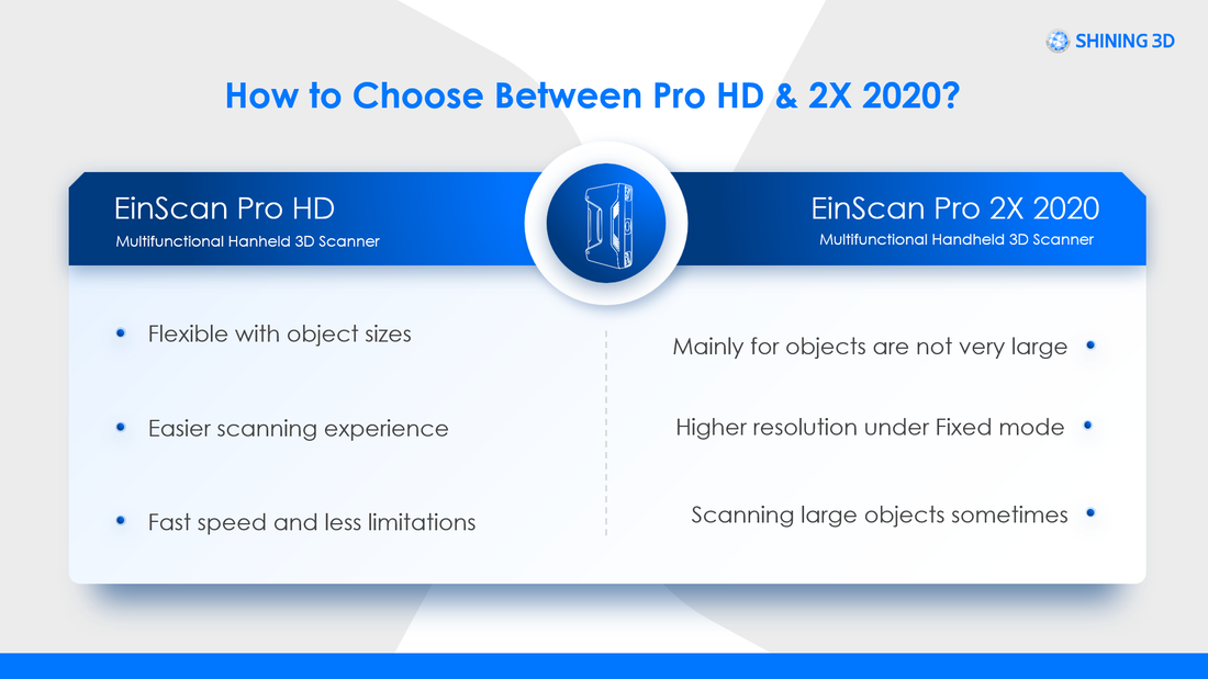
Comparing Einscan Pro HD vs EinScan Pro 2X 2020

You can see that these 2 scanners have a different FOV. Guess which one is better suited for large objects? You probably guessed it right if you followed the logic so far - it's the EinScan Pro HD. Objects that are not very large like within the 3-100mm range, EinScan Pro 2X 2020 is better and it's cheaper too!
|
Of course, this is not absolute as there are other factors like whether the texture is reflective or not. If reflective, Pro HD works better unless you can powder coat the object.
|
Vertical Divider
|
So, keep in mind that there is no one-FOV-fits-all 3D scanner if you want a great 3D scanning output. The first step in choosing a 3D scanner is to confirm the size of the object you need to scan so it can help you determine the FOV of the scanner required. In the next blog, we will help you narrow it down further and together we will look at how the material on the surface of the object can affect your purchase choice.
Watch this webinar on how to select a model if you want to learn further!
Watch this webinar on how to select a model if you want to learn further!
Growshapes the official U.S. distributor of Shining 3D EinScan 3D scanners. We now carry the eviXscan 3D scanner from Evatronix as well!
See the innovators on Growshapes’ social media channels to get the latest expert news on innovation in 3D digitization, then share your thoughts and join the conversation about 3D digital innovation with #digitize3D
See the innovators on Growshapes’ social media channels to get the latest expert news on innovation in 3D digitization, then share your thoughts and join the conversation about 3D digital innovation with #digitize3D
Growshapes
Provider of leading edge 3D scanning products and services. We see 3D!
Archives
July 2024
June 2024
May 2024
March 2024
December 2023
October 2023
June 2023
April 2023
February 2023
October 2022
September 2022
August 2022
May 2022
April 2022
March 2022
February 2022
November 2021
October 2021
August 2021
April 2021
March 2021
January 2021
December 2020
November 2020
September 2020
August 2020
June 2020
April 2020
March 2020
January 2020
December 2019
November 2019
October 2019
June 2019
May 2019
January 2019
December 2018
November 2018
October 2018
September 2018
August 2018
July 2018
June 2018
May 2018
April 2018
March 2018
February 2018
January 2018
December 2017
November 2017
October 2017
September 2017
August 2017
July 2017
April 2017
February 2017
January 2017
December 2016
November 2016
October 2016
July 2016
June 2016
May 2016
April 2016
January 2016
December 2015
November 2015
October 2015
September 2015
July 2015
June 2015
April 2015
March 2015
January 2015
December 2014
November 2014
October 2014
September 2014
August 2014
July 2014
June 2014
May 2014
April 2014
March 2014
February 2014
January 2014
Categories
All
3D Printing
3D Scan File Ouput
3D Scanner Rental
3D Scanner Setup
3D Scanning
3D Scanning Colorful Objects
3D Scanning Dark Surfaces
3D Scanning Faces
3D Scanning Highly Details Objects
3D Scanning Humans
3D Scanning Large Objects
3D Scanning Shiny Surfaces
3D Scanning Small Objects
3D Visualization
Additive Manufacturing
Afinia
Alignment In 3D Scanning
Augumented Reality (AR)
Blue Laser
Blue Light
DAVID 3D Scanners
Design
Desktop 3D Printers
Ecology/Sustainable
Education
EFoil Wing
EinScan 3D Scanners
EinScan 3D Scanner Software
Einscan H
EinScan H2
EinScan HX
EinScan Pro 2X
EinScan Pro 2X 2020
EinScan Pro 2X Plus
EinScan Pro HD
EinScan SE/SP
Einstar
Engineering
Evatronix EviXscan
Field Of View
FormLabs
Geomagic
HP Structured Light Scanner Pro S3
Industrial Kit
Infrared
Laser 3D Scanning
MacOS
Makerbot
Makerspace
Market SIze
Mcor IRIS 3D Printer
Medical
Mesh Optimization
Netfabb Software
Open Technologies Cronos 3D Scanner
Orthotics And Prosthetics
Product Developers
Prototyping
Reverse Engineering
Shining3D
Software Updates
Solid Edge Software
Structured Light 3D Scanning
Transcan C
White Light
Workforce Development
 RSS Feed
|
Vertical Divider
GROWSHAPESStay connected |
Menu |


|
©2024 Growshapes LLC. All rights reserved.