LET'S TALK ABOUT 3D SCANNING |

|
In the realm of 3D scanning and modeling, various file export formats serve specific purposes, each type of file with its characteristics and applications. Whether you're involved in digital manufacturing, use 3D scanning to scan a physical part as a reverse engineering method for rapid prototyping, or want to create a digital version of a physical product for your digital animation, choosing the correct file type is crucial for ensuring compatibility and maintaining the integrity of your 3D surface models. In this blog post, we'll explore several common 3D scanner file formats that can be produced after the 3D scanning process. Types of output data format are ASC, P3, STL, PLY, OBJ, and 3MF, providing insights into what they are and how they are typically used. 1. ASC File (ASCII Point Cloud) Description: ASC files, also known as ASCII Point Cloud files, are plain text files that store 3D point cloud data. Each line in the file represents a point in 3D space, defined by its X, Y, and Z coordinates storing the position information of each point. Optionally, additional data such as color information (RGB values) or intensity may be included for each point. Purpose: ASC files are often used to store point cloud data captured from 3D scanning devices. They provide straightforward raw scan data for storing large sets of point clouds, which can then be processed for various applications such as reverse engineering, metrology, and digital preservation. 2. P3 File (ASCII Polygon File) File Description: P3 files are ASCII-based polygon mesh models that describe 3D geometry using vertex, edge, and polygon definitions. Each line in the file typically represents a vertex or polygon face, with additional information such as vertex normals and texture coordinates if applicable. Purpose: P3 files are commonly used for representing 3D polygonal meshes, making the final polygon file suitable for applications such as computer-aided design (CAD), visualization, and digital content creation (DCC) for animation and gaming. 3. STL File (Stereolithography) Description: STL files are one of the most widely used surface model file formats for 3D printing and the best option and best for exporting to CAD applications. They represent 3D surfaces as a collection of interconnected triangles (mesh data). STL files can be either ASCII or binary, with binary being more common due to a smaller file size. Purpose: The STL file format is ideal for 3D printing as it describes the surface geometry of an object using triangular facets. STL format is the most common file type of exported files into CAD software or reverse engineering software to create a solid model and add parametric features for reverse engineering, prototyping, and manufacturing, providing a universal format for exchanging 3D model data. 4. PLY File (Polygon File Format) Description: PLY files are flexible file formats that support a variety of properties for each vertex, such as color, transparency, and surface normals. They can store both ASCII and binary data, making them versatile for different applications. Purpose: PLY files are used in 3D scanning, computer graphics, and computational geometry. They are suitable for capturing detailed surface model information and are often used in applications requiring high-resolution representations of 3D objects. 5. OBJ File (Wavefront OBJ) Description: OBJ files are widely used for storing geometric data, including vertex positions, texture coordinates, vertex normals, and material definitions. They are ASCII-based and support basic geometric shapes as well as complex polygonal meshes. Purpose: OBJ files are popular in 3D modeling and rendering software, including animation and gaming. They are versatile for exchanging 3D models between different software packages and are supported by most CAD files and 3D graphics programs. 6. 3MF File (3D Manufacturing Format) Description: 3MF files are a modern file format designed specifically for additive manufacturing (3D printing). They can store a wide range of data including geometry, materials, textures, colors, and metadata in a single file. Purpose: 3MF files streamline the workflow from design to manufacturing by encapsulating all necessary information within a single file. They support advanced features such as lattice structures and multiple materials, promoting interoperability and efficiency in 3D printing workflows. Conclusion Choosing the right 3D scan file format for your new project depends on your specific application and workflow requirements. Whether you're capturing point cloud data from a 3D scanner, preparing models for 3D printing, or creating digital content for animation, understanding the characteristics and purposes of each file type is essential for achieving optimal results. By leveraging the capabilities of ASC, P3, STL, PLY, OBJ, and 3MF files, you can implement best practices while effectively managing and exchanging 3D data files across different platforms and industries, driving innovation and creativity in the world of 3D technology. Growshapes the official U.S. distributor of Shining 3D EinScan 3D scanners. We now carry the eviXscan 3D scanner from Evatronix as well!
See the innovators on Growshapes’ social media channels to get the latest expert news on innovation in 3D digitization, then share your thoughts and join the conversation about 3D digital innovation with #digitize3D
0 Comments
The new EXScan Pro V4.0 for the EinScan Pro series 3D scanners is a game-changer, delivering substantial improvements and innovative features to elevate your 3D scanning experience. From background segmentation to real-time marker recognition, automatic plane segmentation, and marker/point cloud editing, every feature is crafted to enhance precision and efficiency. The upgraded post-processing and measurement features, coupled with a user-friendly interface and additional functionalities, underscore our commitment to providing a seamless and enriched scanning experience for EinScan users. Watch the video to find out more! New Features for Fixed Scan Mode
New Features for Handheld Scan Mode
Upgraded Post Processing Features
Integration Upgrades
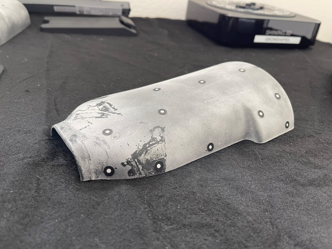
Growshapes the official U.S. distributor of Shining 3D EinScan 3D scanners. We now carry the eviXscan 3D scanner from Evatronix as well! See the innovators on Growshapes’ social media channels to get the latest expert news on innovation in 3D digitization, then share your thoughts and join the conversation about 3D digital innovation with #digitize3D Are you still using calipers? Have you tried reverse engineering using 3D scanners? It's a new tool for an old task. Merriam-Webster defines reverse engineering as "the process of disassembling and examining a product or device to discover the concepts involved in its manufacture, usually with the goal of producing something similar." As the design process is beoming digitized, reverse engineering today is more commonly associated with the process of converting a physical object’s geometry into a digital 3D model and replicating the original design or further improving for new manufacturing processes such as additive manufacturing. More engineers are moving away from using calipers and adopting 3D scanners to take measurements, especially of complex parts. 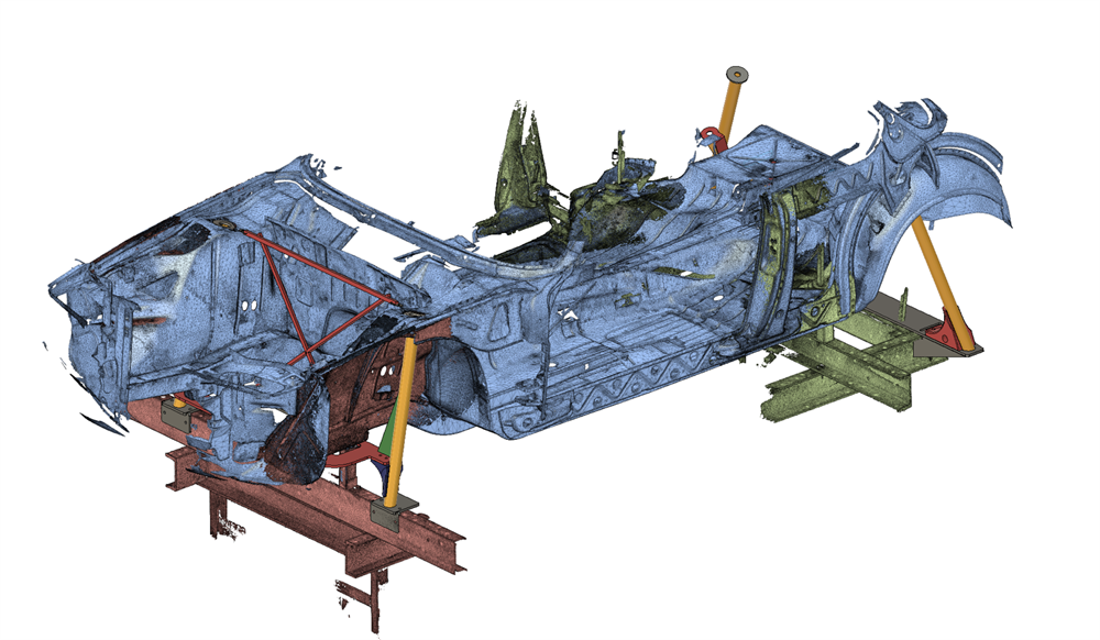 Reverse Engineering Model, Courtesy of Shining 3D 3D scanners allows you to digitally capture the geometry of even the most complex parts in an extraordinarily quick and precise manner. A large docking pump was recently captured in just 20 minutes for example, with the help of laser 3D scanning. This technology has enabled the use of reverse engineering in situations beyond simple benchmarking and part reproduction, as we explore in the next section. Main Applications for 3D Scanning & Reverse Engineering Reverse engineering with 3D scanning offers many possibilities for product development and manufacturing. Overall, the different uses of reverse engineering can be divided into three major applications: (1) to replicate parts, (2) to create variations of existing parts, or (3) to develop entirely new parts based on an existing environment or object. Let's look at each application in a bit more detail. 1. Recreate & Replicate Parts One of the most popular uses for 3D scanners is recreating damaged or worn-out parts that are unavailable from the original supplier or lack proper documentation. This is a common problem when working with old machinery or vintage vehicles, and it’s always challenging to do with manual reverse engineering tools like calipers. However, with a good 3D scanner and the proper software, it can become a straightforward task. Katsuya Tanabiki, for example, shared his process of reverse engineering a shield notch on an old motorcycle helmet. The helmet featured two shield notches, but one was broken, and it was too difficult to obtain a replacement notch. This tiny part was 3D scanned with an EinScan Pro 2X in Fixed Mode, and later 3D printed.
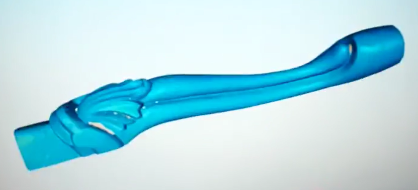
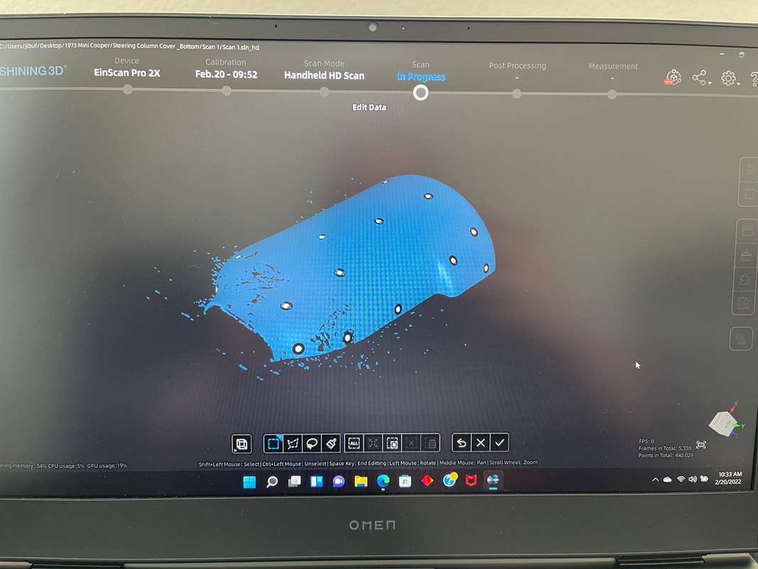
2. Improve The Design of Existing Parts Another goal of reverse engineering is to use digitized parts to create new and improved variants instead of merely reproducing them. This method can significantly reduce the time and costs of creating parts from scratch and also ensures a perfect fit for components belonging to larger assemblies. Taiwanese company Kiden Design has illustrated the reverse engineering process of optimizing a pipe using 3D scanning, CAD, and 3D printing. The EinScan Pro HD 3D scanner, used in Handheld mode, captured the irregular geometry of the pipe on two opposite sides that were stitched together later in software. Thanks to the accurate 3D model obtained, the geometry could be easily optimized in CAD. 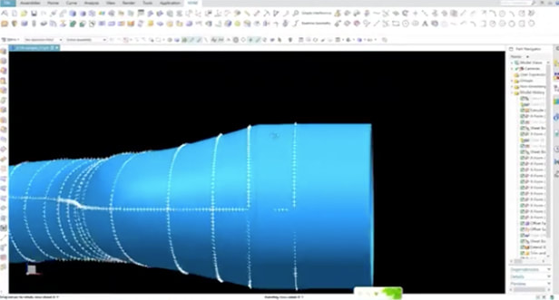 Optimizing the Pipe Design Photo: Courtesy of Shining 3D
3. Create & Design Entirely New Parts Another application for reverse engineering is where a part is digitized as a reference to create entirely new parts. This procedure is usually employed when a tight fit is required on an existing part that is too complex or has an irregular interface.
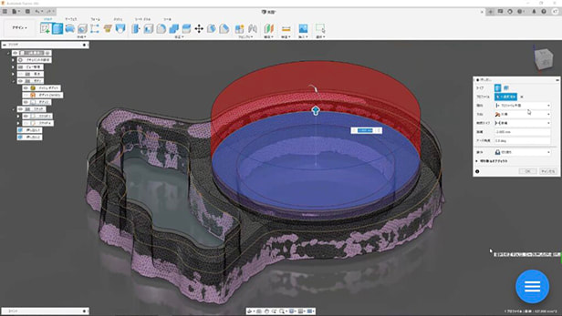
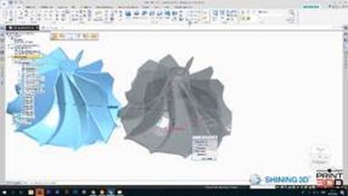
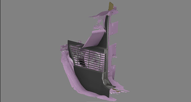
This particular technique is also commonly practiced by medical professionals since body parts are unique and challenging to accurately replicate using manual methods. Here, 3D scanning once again has proven to be an efficient tool for digitizing human parts and surfaces. Earmolds, for example, are patient-specific parts that help conduct sound from the hearing aids to the ear canal. Servicing or creating new earmolds from scratch can take several weeks during which patients experience hearing problems without them. However, thanks to reverse engineering methods with 3D scanning and 3D printing, the Hearing Beyond Audiology Clinic in Toronto can produce temporary earmolds in just one day. The temporary accessory allows patients to keep their hearing while waiting for the earmolds to be produced or serviced in other facilities. Similar reverse engineering methods with 3D scanning are also utilized for producing facial prosthetics and custom orthotics. 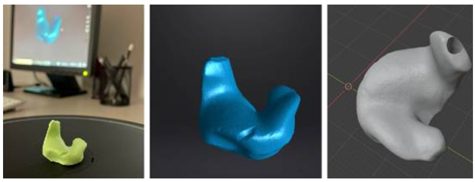 Earmolds Photo: Courtesy of Shining 3D Quality Data Capture Is Key for Successful Reverse Engineeing The use cases above clearly demonstrate the central role of 3D scanning in reverse engineering. It comes as no surprise that the effectiveness and accuracy of data captured by 3D scanning are crucial for a successful reverse engineering process. Yet, the software tools used for processing the data and working with the 3D models are also essential for achieving the desired results in reverse engineering. To understand the importance of good data and adequate software, let’s go over the main steps of reverse engineering with 3D scanning. Step 1. Data acquisition The very first step in any reverse engineering process is data acquisition. Regardless of the method, proper planning and preparation can make the difference between good and poor data. With 3D scanning, this involves selecting the correct device for the job, including the proper configuration (handheld or stationary) and accessories such as turntables, fixtures, and calibration panels. Correct calibration of the device is also vital to acquire quality data. The regions or parts to be digitized usually demand some kind of preparation. Besides a good cleaning, some 3D scanning devices also require the use of markers or even special coatings on reflective surfaces. One should also consider the ambient conditions before starting the digitization process. A controlled environment (e.g. indoors, without direct sunlight, a cleared tabletop, …) is always preferred to reduce noise in the data, but that’s not always possible. All the factors mentioned will contribute to proper data collection, which will in turn determine how quickly and easily the data can be processed next. Step 2. Post-Processing The next step in a reverse engineering process is post-processing the acquired data, or the “point cloud”. Here, the point cloud is processed by software tools – like EinScan software – resulting in a 3D mesh representation of the digitized object. 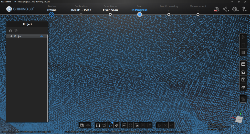 Point Cloud Image In any case, the 3D model in this initial stage usually requires some refinement like removing unwanted captured data, repairing surfaces, and filling gaps per below. 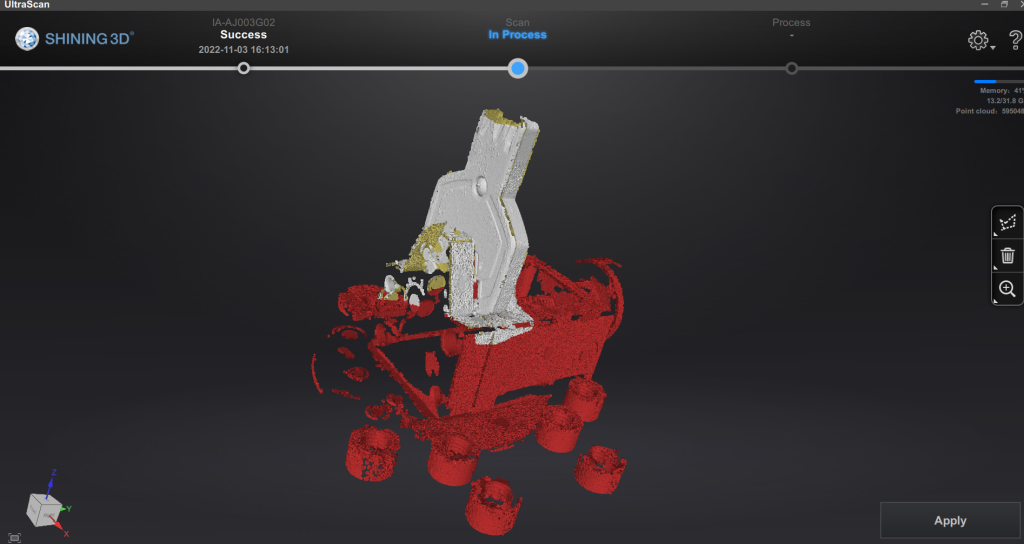 3D mesh data editing, Courtesy of Shining 3D The better the data quality acquired, the less post-processing and repairing will be needed. The post-processing step is also when reference entities are assigned to the 3D model, a procedure that should expedite the next stage of the reverse engineering process. Step 3. CAD Model Generation The final step in a reverse engineering process is to convert the mesh representation of the physical object captured by the 3D scanner into a solid 3D model. 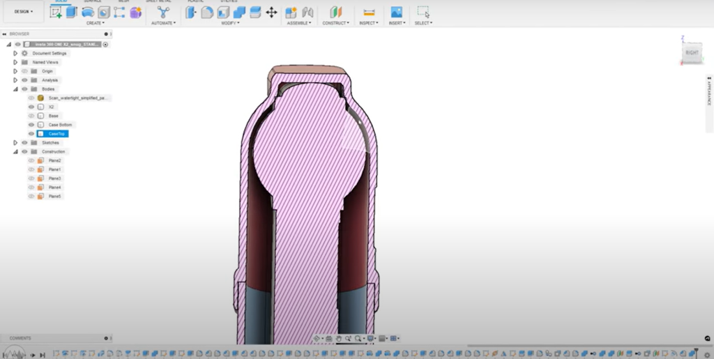 CAD Model from 3D Scan Photo: Courtesy of Shining 3D As accurate as the mesh model can be, it is inadequate for most reverse engineering applications that require additional handling like fixing any physical damage, creating variations, or designing new parts altogether. In this stage, the refined mesh model from the previous step works as an exact reference model for recreating the model using parametric CAD tools. Although in theory any general-purpose CAD program could handle this, specially purposed software geared towards reverse engineering can make the process much easier and yield much better results too. An appropriate CAD software for reverse engineering can also compare the digitized model to the parametric one, allowing users to check for geometrical and dimensional differences. Conclusion Reverse engineering has come a long way and 3D scanning technologies have broadened the range of industrial applications for reverse engineering, benefiting both businesses and consumers. The quality of the captured data is crucial to obtain good results in reverse engineering. The choice of the 3D scanning device, as well as its capabilities and functions, play a central role in the success of the entire process. Read further about how to make sure you choose the right model for your project here. Though often overlooked or underestimated, the software used in the later stages of reverse engineering also bears great importance. Specific built-in tools for the job can make a big difference in a well-executed reverse engineering process. Growshapes the official U.S. distributor of Shining 3D EinScan 3D scanners. We now carry the eviXscan 3D scanner from Evatronix as well!
See the innovators on Growshapes’ social media channels to get the latest expert news on innovation in 3D digitization, then share your thoughts and join the conversation about 3D digital innovation with #digitize3D In 3D scanning, accuracy is a key metric in choosing which model to use for your project. How accurately do you need to replicate the physical model? In other words, how authentic do you want the 3D digital model of the real object to be? High end 3D scanners like eviXscan Quadro+ can achieve up to 0.007mm (7 microns) accuracy, while lower end 3D scanners like EinScan SP can still achieve an accuracy up to 0.05mm (50 microns). Accuracy of a 3D scanner depends on the quality of the camera, projector lights as well as the software. Meanwhile there is another important metric, resolution. Resolution is about defining the point distance the 3D scanner can capture to generate the point cloud which is then converted into a mesh. If you 3D scan your object in high resolution, the point distance is small thus details will be more visible, while if you 3D scan your object in low resolution, the point distance is bigger. 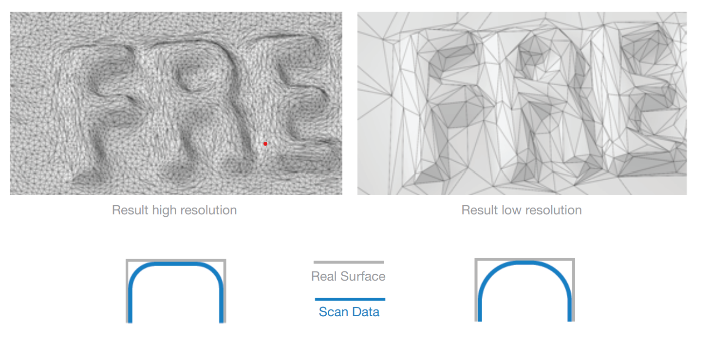
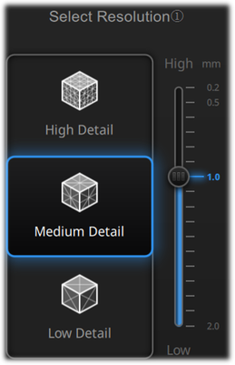
Below is a guideline of resolution settings that is optimal depending on the type of objects you are 3D scanning. Basically the recommendation is the smaller the object, use high detail (higher resolution) and the larger the object, use low detail (lower resolution) settting. 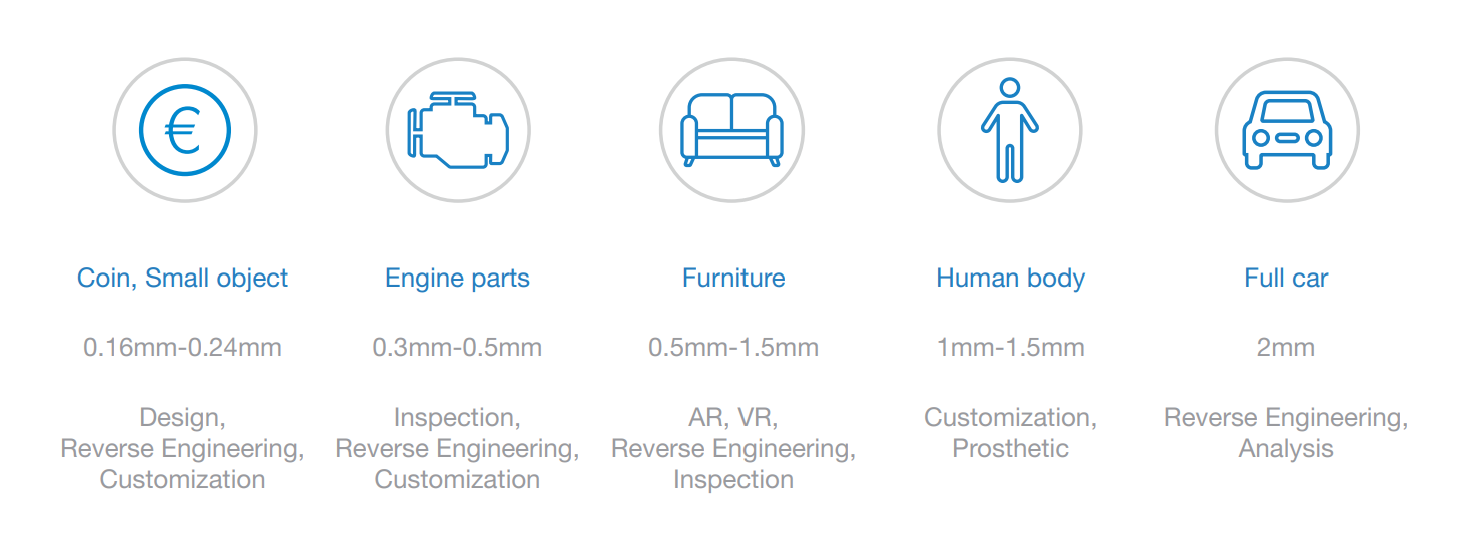 The Einscan Pro HD and EinScan 2X 2020 provde super high resolution with HD scan mode and setting the resolution to "High Detail". This kind of high detail captures is useful for objects with that has a lot of details like the object below. On the other hand, large engineering parts may not require such detail but higher accuracy. 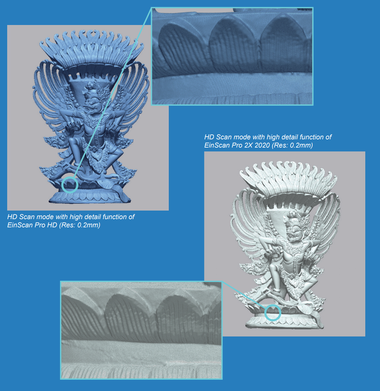 Basically the tip is to think about what you are going to do about your 3D scan file and choose the right resolution setting depending on the object you are 3D scanning. Growshapes the official U.S. distributor of Shining 3D EinScan 3D scanners. We now carry the eviXscan 3D scanner from Evatronix as well!
See the innovators on Growshapes’ social media channels to get the latest expert news on innovation in 3D digitization, then share your thoughts and join the conversation about 3D digital innovation with #digitize3D Solid Edge 2021 brought us powerful performance updates to make our working flow more efficient in the areas of Reverse Engineering as well as Part Modeling, and this year, it moves further, launching the promising and practical next generation design functions, Subdivision Modeling and Convergent Modeling. Let´s take a look at the detailed updates of Solid Edge 2022 and discover its advantages and innovations. Please note:
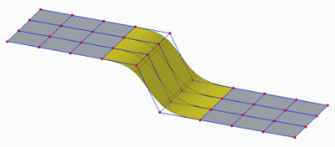
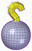
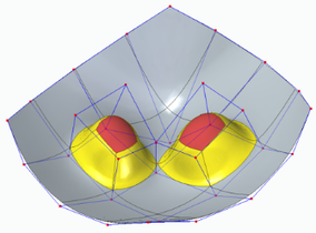
Subdivision Modeling EnhancementsSubdivision Modeling makes it easier to generate a stylized body and control its shape by using a polygonal cage. Solid Edge 2022 introduces new modification functions. 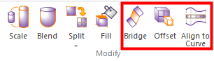 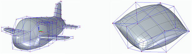 Bridge In the Subdivision Modeling environment, you can use the new "Bridge" command to create a loft-like feature that connects edges or faces selected on a single cage or two separate cages.
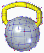
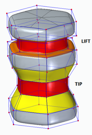
Offset Cage Faces Offset allows users to select faces of a cage and offset them along their normal direction. Offset allows users to select faces of a cage and offset them along their normal direction. Offset allows users to select faces of a cage and offset them along their normal direction
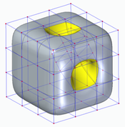
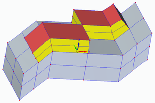
Split with Offset Allows adding local detail to model without having to split the entire model, use the new "Split with Offset" command to add detail to a face by offsetting the new faces inward by a user-defined amount. 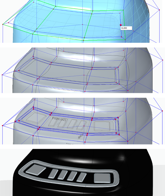 Align to Curve Use the new Align to Curve command to fit the vertices of body cage faces to one or more existing curves or to curves you interactively sketch. You can undo and redo each curve edit until you achieve the desired shape. 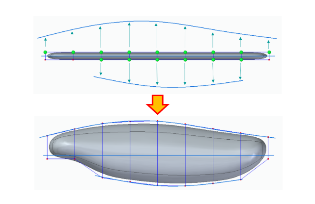 Convergent ModelingSolid Edge now supports mixed mesh modelling (a.k.a Hybrid Convergent modelling). Mesh and Classical faces are in one body, this is extremely helpful when you do assembly reverse engineering and 3D printing. 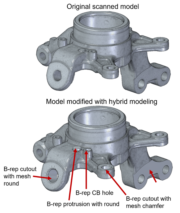 The new "Show Facet Edges" command controls the display of facet edges within a model. When selected, the command displays the facets; when deselected, the facet edges are not displayed. 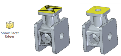 Reference Point Cloud
With all new features, Solid Edge 2022 Shining 3D Edition allows you to do more with your scanned data. It is the practical and efficient solution for engineers, designers and 3D enthusiasts for sure. Growshapes the official U.S. distributor of Shining 3D EinScan 3D scanners. We now carry the eviXscan 3D scanner from Evatronix as well!
See the innovators on Growshapes’ social media channels to get the latest expert news on innovation in 3D digitization, then share your thoughts and join the conversation about 3D digital innovation with #digitize3D Challenge: Finding replacement parts for a classic car
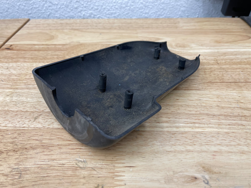
Solution: EinScan Pro 2X fills the gap John, also being a talented engineer and with his deep knowledge of 3D printing technology, he decided to reverse engineer these Mini Cooper steering column covers and 3D print new replacement parts. Rather than measuring the parts with a caliper and designing in CAD from scratch, John decided to 3D scan the plastic steering column covers to generate a 3D digital surface model to get accurate measurements of the parts with the EinScan Pro 2X 3D scanner
 The EinScan Pro 2X 3D scanner with the Industrial Kit enabled John to put the object on the turntable and within an hour or so, get a workable 3D mesh. Multiple scans were automatically fused together to create a watertight 360-degree digital surface mesh that was then imported into the Solid Edge Shining 3D Edition reverse engineering software. The surface mesh files were leveraged to build a solid model, make design improvements, and then be further process for 3D printing. Results: Capturing details enabled precise CAD file creation for 3D printing
“By using the 3D scanner, I was able to focus on creating the CAD file suitable for 3D printing without having to wrestle with measurements and generating a CAD file from scratch.” - John Buffington. Also importatnt to note is to understand copyright laws in the US. Reverse engineering is legal but if you are going to reproduce and profit, you should get in touch with a patent lawyer. With an old part like above, it's beyond the copyright Growshapes the official U.S. distributor of Shining 3D EinScan 3D scanners. We now carry the eviXscan 3D scanner from Evatronix as well!
See the innovators on Growshapes’ social media channels to get the latest expert news on innovation in 3D digitization, then share your thoughts and join the conversation about 3D digital innovation with #digitize3D 3D scanner is a data-acquiring device that captures the surface model of a physical object in a digital polygonal model. The types of output data format that 3D scanners can generate maybe confusing. What is an ASC file? Which export formats does my CAD software import for rapid prototyping? What is the best practice for saving scans? Which file format is the best choice for 3D printing? In this post, we will discuss all file types that involve Einscan software. The type of file you require depends on what you are going to do after the scanning process. There are a total of 6 types of output data formats (ASC, p3, STL, PLY, OBJ, 3MF) that you can export from EinScan software during data capture and generating mesh which are polygon models. We will explain the differences among these 6 file types in this blog. Point Cloud Data Format When you have finished your scan and are ready to convert your raw scan data to point cloud data, you can click on the save button to save the point cloud data as an ASC file and the marker position as p3 format when markers are detected. ASC file contains the position information of each point in the point cloud. This file type can be opened in most scan data processing software and metrology software like Meshmixer, GOM Inspect, and Geomagic Essentials. The P3 file is for marker reuse purposes in EinScan software. For a large object scan, the user can scan all markers only first and save the marker frame as a p3 file. Later the object can be scanned part by part in a separate project using the same p3 file as a reference which improves the accuracy and will require no alignment between each project. 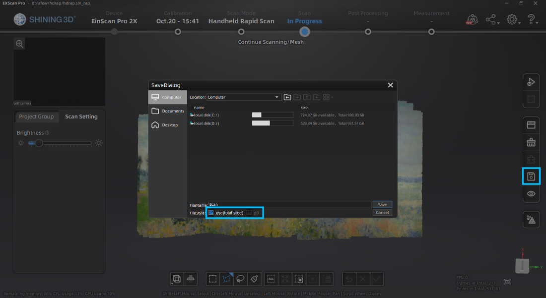 With Fix scan mode number of scans will be saved as separate files, while for handheld scans the full point cloud will be saved as one file. Meshed Data File Format After the data is meshed, more saving options will be available. ASC file is still available while the mesh can be saved as STL, PLY, OBJ, or 3MF files. STL file format is the most common mesh file format. It only contains the position and normal directions of all triangles in the mesh. This polygon file format can be opened by mesh editing software and many CAD software like Solid Edge or Solidworks for reverse engineering. PLY and OBJ file formats contain mesh texture information, including color information, in addition to the STL file. Users can export these data types for digital documentation and online model display. 3MF file is the 3D printing format published by the 3MF Consortium. This format includes information about materials, colors, and other information that cannot be represented in the STL format. Windows system and other CAD software packages can open this mesh format. 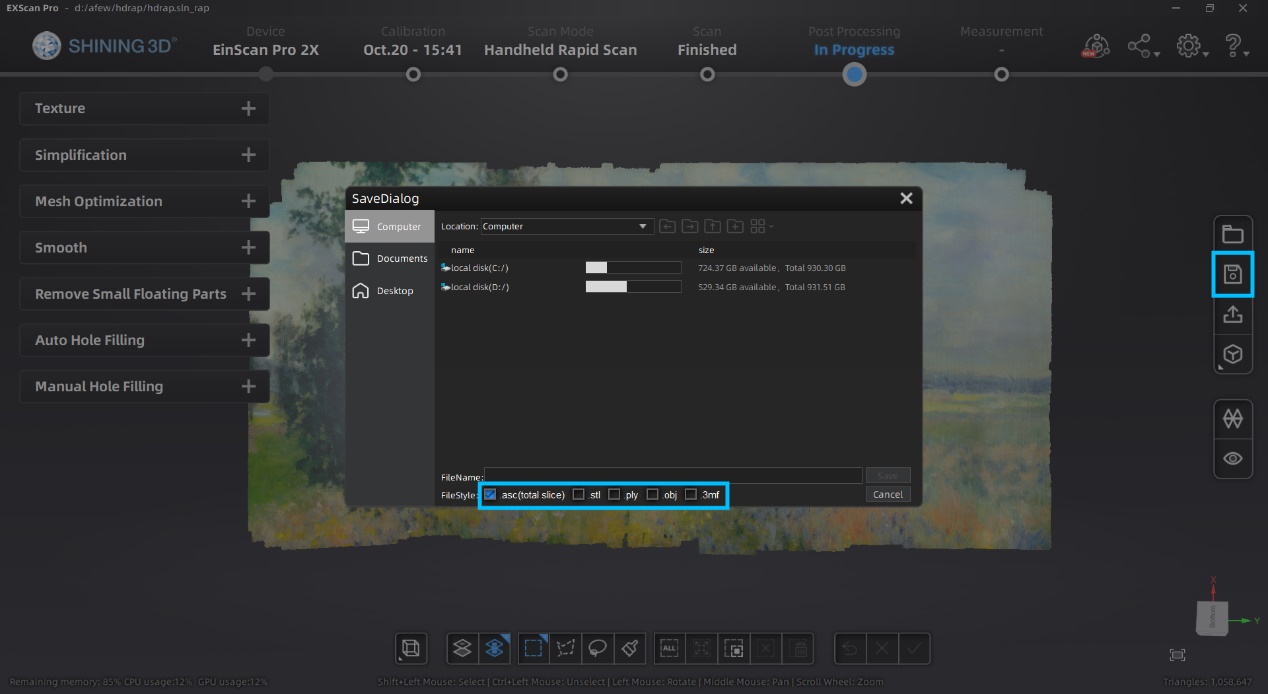 Post Processing Data EinScan software provides basic functions for mesh editing in Post Processing and Measurement sections. Usually, users use these functions right after meshing data. However, external mesh data can also be imported into the EinScan software for editing. The EinScan software supports STL, OBJ, and PLY formats for post-processing and measurement. 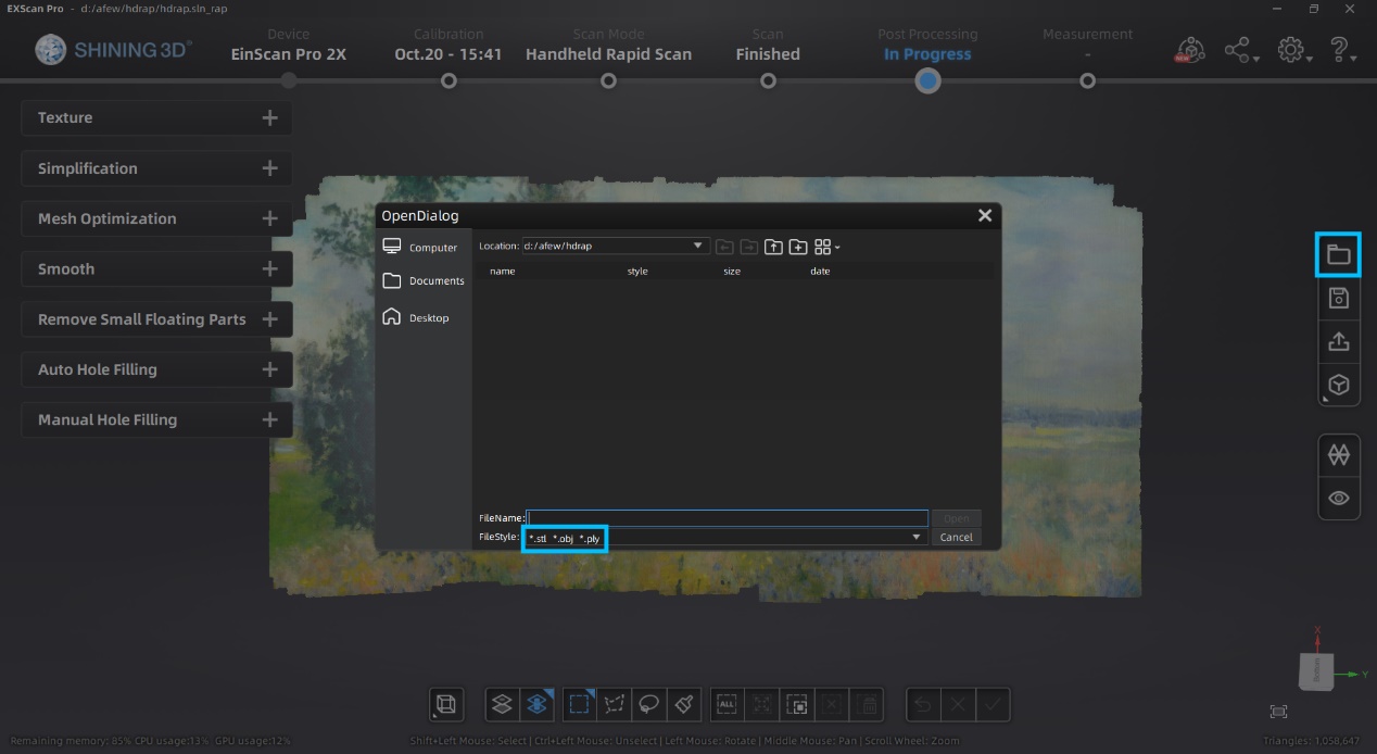
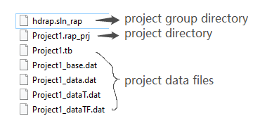
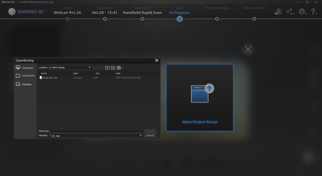
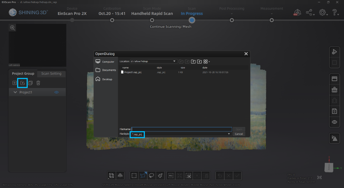
The project group folder contains different kinds of files. The project group directory links all projects in the group. The project directory links all data files belonging to this project and the rest are project data files. When moving the project group, the user needs to move all the folders in the project group. When opening the project, the user needs to locate the folder where the project group was saved and open the corresponding directory files.The project group folder contains different file formats. The project group directory links all projects in the group. The project directory links all data files belonging to this project and the rest are project data files. When moving the project group, the user needs to move all the folders in the project group. When opening the project, the user must locate the folder where the project group was saved and open the corresponding directory files.
So that's it! You have 6 output formats to choose from and all the required scans for your saved project will be in a project group folder. Remember, the file size for each project is large, so make sure you secure a space on your PC where you can save the files. Growshapes the official U.S. distributor of Shining 3D EinScan 3D scanners. We now carry the eviXscan 3D scanner from Evatronix as well!
See the innovators on Growshapes’ social media channels to get the latest expert news on innovation in 3D digitization, then share your thoughts and join the conversation about 3D digital innovation with #digitize3D |
GrowshapesProvider of leading edge 3D scanning products and services. We see 3D! Archives
July 2024
Categories
All
|


 RSS Feed
|
Vertical Divider
GROWSHAPESStay connected |
Menu |


|
©2024 Growshapes LLC. All rights reserved.