LET'S TALK ABOUT 3D SCANNING |

|
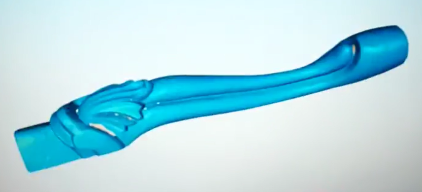
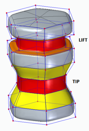
In the ever-evolving world of watersports, efoiling has taken the spotlight with its thrilling combination of surfing and flying above water. Efoil boards, propelled by electric motors, offer an exhilarating experience, and at the heart of their performance lies the efoil wing. However, this industry is young and manufacturers struggle to survive such as FOIL Inc (getfoil.com) as there is not enough demand out there leaving enthusiasts in a lurch when their favorite wing model is no longer available to purchase and the original designs may be lost. Fortunately, 3D scanning and reverse engineering offer a lifeline for reviving these designs. In this blog post, we'll explore how you can use 3D scanning technology to bring an out-of-production foil wing back to life. Importance of the Efoil Wing The efoil wing is crucial for the lift and stability of the board, directly affecting the rider's experience. Each wing model has its unique design that caters to different riding styles, water conditions, and skill levels. When a beloved wing is no longer produced, finding a suitable replacement can be challenging, making reverse engineering an appealing solution. We have 3D scanned the efoil wing 200 of the FOIL series using the EinScan Pro HD with high accuracy as the initial step to enable full reverse engineering and manufacturing. PART I: 3D SCANNNING TO CAPTURE THE ACCURATE SIZE AND CURVATURE Step 1: Preparing for 3D Scanning Before diving into the scanning process, you'll need the right tools and a suitable environment. Here is what we used.
 EinScan Pro HD and the Wing prepared with markers
Step 2: 3D Scanning the Efoil Wing
Step 3: Post Processing
 Aligning the Front & Back Scans  Post-Processed 3D Scan Mesh File Here is the STL file so you can further reverse engineer and manufacture via 3D printing!
PART II: REVERSE ENGINEERING
PART III: MANUFACTURING Once satisfied with the redesigned model, it's time to manufacture the wing.
CONCLUSION 3D scanning and reverse engineering provide a powerful combination for resurrecting discontinued efoil wings. By capturing the precise geometry of a classic wing and using modern tools to refine and replicate its design, enthusiasts can continue to enjoy their favorite efoil experiences. Whether you're an efoil aficionado or a watersports innovator, this technology opens up a world of possibilities for preserving and enhancing the sport. So, don't despair about FOIL Inc going bust, let technology breathe new life into it! Growshapes the official U.S. distributor of Shining 3D EinScan 3D scanners. We now carry the eviXscan 3D scanner from Evatronix as well!
See the innovators on Growshapes’ social media channels to get the latest expert news on innovation in 3D digitization, then share your thoughts and join the conversation about 3D digital innovation with #digitize3D
0 Comments
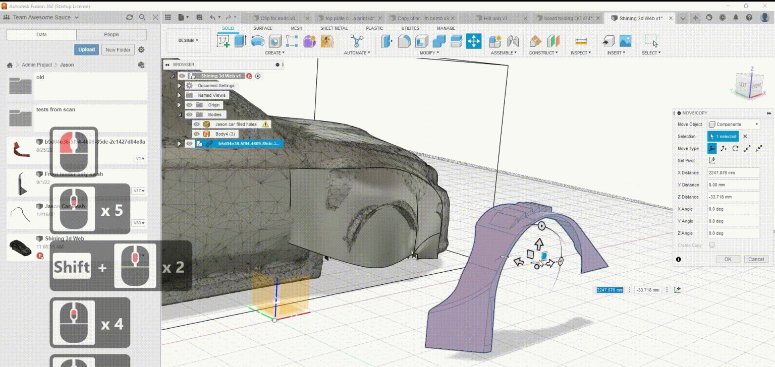
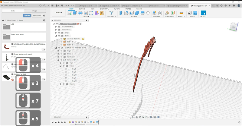
Edward Van Zyl, a seasoned 3D scanning and printing expert from Manitoba, heads the company Dreamworks 3D Printing and Scanning. With extensive expertise in vintage car restoration and customization, he is enthusiastic about utilizing state-of-the-art equipment to capture intricate details of automotive components and then utilizing software to generate accurate 3D models. This article, courtesy of Shining 3D, deep dives into the tips utilized by Edward for scanning with the EinScan HX Hybrid Light Source Handheld 3D Scanner and the reverse engineering of car parts through the use of Geomagic Essentials and Fusion 360. Scanning And Printing An Arrow 50 Scooter Part Edward embarked on a projet to 3D scan and reverse engineer an Arrow 50 scooter part and then 3D print. He chose the EinScan HX Hybrid Light Source Handheld 3D Scanner for this reverse engineering project. In the 3D scanning process, Edward provides a small tip: utilizing miniature pyramids as markers rather than some of the markers that need to be put directly onto the object. This has the advantage of saving time and cost, as it eliminates the need for post-scan cleaning and the small pyramids can be reused. You may download files of pyramids here. Arrow 50 Scooter Part & Pyramid Markers Photo: Courtesy of Shining 3D In laser scan mode, EinScan HX has a maximum scan speed of 480,000points/s. It just took around 12 minutes to complete the whole scan of the component. And the laser scan mode of EinScan HX makes the scanned data accurate up to 0.04mm, thus you get a very accurate model for subsequent work. Scan File generated by EinScan HX Photo: Courtesy of Shining 3D Below is the 3D printed part from Bambu Lab X1-Carbon Combo 3D Printer. 3D Printed Part Photo: Courtesy of Shining 3D Cutting A Fender Using Geomagic Essentials Edward’s goal was to cut a fender and make sure it was the right size for installation. Usually, he will print out the part for test, and in this case he offers an easy-to-print and material-saving trick. He creates a small offset about 5 mm or even less, and cuts the part again, so that he gets a tiny piece of the fender, but maintains the geometry he need. 3D printing this thin piece was just as good for installation testing, and using only a minimal amount of printed material.
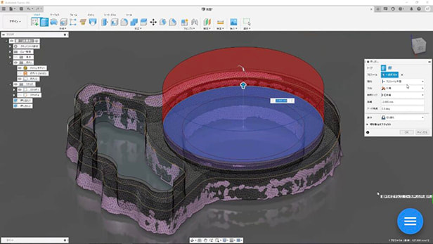
Reverse Engineering An Engine Using Geomagic Essentials And Fusion 360 Furthermore, Edward uses Geomagic Essentials to extract features on the engine, and then using Fusion 360 to model the three holes in which he wants to simulate the mounting bolts. 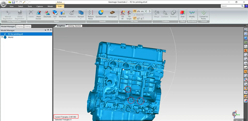 Extracting features in Geomagic Essentials Photo: Courtesy of Shining 3D One thing to keep in mind here is that you need to maintain the mesh and the extracted features in uniform coordinates. This step ensures that the extracted features can be overlayed on the mesh in the right position. After extruding two cylinders of different sizes and modeling some threads, the mounting bolt is done. 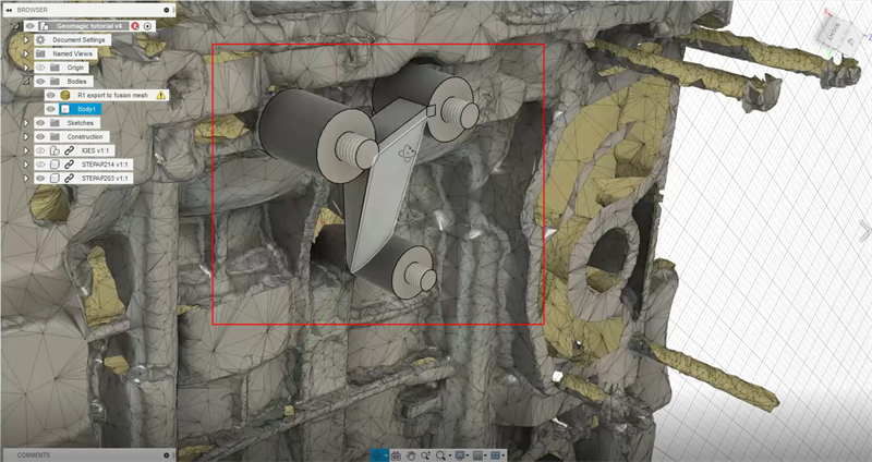 Modeled Mounting Bolts and Brackets Photo: Courtesy of Shining 3D This is basically how to go from scanning to printing of a part; how to use a mesh and model mounting bolts in Geomagic Essentials and Fusion 360. And it is clear how much can be done with a bundle of 3D scanners and softwares. You may find more operation details in the playback video. If you found this content useful, please follow Shining 3D's webinar pages, so you won’t miss out on more information. Growshapes the official U.S. distributor of Shining 3D EinScan 3D scanners. We now carry the eviXscan 3D scanner from Evatronix as well!
See the innovators on Growshapes’ social media channels to get the latest expert news on innovation in 3D digitization, then share your thoughts and join the conversation about 3D digital innovation with #digitize3D Are you still using calipers? Have you tried reverse engineering using 3D scanners? It's a new tool for an old task. Merriam-Webster defines reverse engineering as "the process of disassembling and examining a product or device to discover the concepts involved in its manufacture, usually with the goal of producing something similar." As the design process is beoming digitized, reverse engineering today is more commonly associated with the process of converting a physical object’s geometry into a digital 3D model and replicating the original design or further improving for new manufacturing processes such as additive manufacturing. More engineers are moving away from using calipers and adopting 3D scanners to take measurements, especially of complex parts.  Reverse Engineering Model, Courtesy of Shining 3D 3D scanners allows you to digitally capture the geometry of even the most complex parts in an extraordinarily quick and precise manner. A large docking pump was recently captured in just 20 minutes for example, with the help of laser 3D scanning. This technology has enabled the use of reverse engineering in situations beyond simple benchmarking and part reproduction, as we explore in the next section. Main Applications for 3D Scanning & Reverse Engineering Reverse engineering with 3D scanning offers many possibilities for product development and manufacturing. Overall, the different uses of reverse engineering can be divided into three major applications: (1) to replicate parts, (2) to create variations of existing parts, or (3) to develop entirely new parts based on an existing environment or object. Let's look at each application in a bit more detail. 1. Recreate & Replicate Parts One of the most popular uses for 3D scanners is recreating damaged or worn-out parts that are unavailable from the original supplier or lack proper documentation. This is a common problem when working with old machinery or vintage vehicles, and it’s always challenging to do with manual reverse engineering tools like calipers. However, with a good 3D scanner and the proper software, it can become a straightforward task. Katsuya Tanabiki, for example, shared his process of reverse engineering a shield notch on an old motorcycle helmet. The helmet featured two shield notches, but one was broken, and it was too difficult to obtain a replacement notch. This tiny part was 3D scanned with an EinScan Pro 2X in Fixed Mode, and later 3D printed.
2. Improve The Design of Existing Parts Another goal of reverse engineering is to use digitized parts to create new and improved variants instead of merely reproducing them. This method can significantly reduce the time and costs of creating parts from scratch and also ensures a perfect fit for components belonging to larger assemblies. Taiwanese company Kiden Design has illustrated the reverse engineering process of optimizing a pipe using 3D scanning, CAD, and 3D printing. The EinScan Pro HD 3D scanner, used in Handheld mode, captured the irregular geometry of the pipe on two opposite sides that were stitched together later in software. Thanks to the accurate 3D model obtained, the geometry could be easily optimized in CAD.  Optimizing the Pipe Design Photo: Courtesy of Shining 3D
3. Create & Design Entirely New Parts Another application for reverse engineering is where a part is digitized as a reference to create entirely new parts. This procedure is usually employed when a tight fit is required on an existing part that is too complex or has an irregular interface.
This particular technique is also commonly practiced by medical professionals since body parts are unique and challenging to accurately replicate using manual methods. Here, 3D scanning once again has proven to be an efficient tool for digitizing human parts and surfaces. Earmolds, for example, are patient-specific parts that help conduct sound from the hearing aids to the ear canal. Servicing or creating new earmolds from scratch can take several weeks during which patients experience hearing problems without them. However, thanks to reverse engineering methods with 3D scanning and 3D printing, the Hearing Beyond Audiology Clinic in Toronto can produce temporary earmolds in just one day. The temporary accessory allows patients to keep their hearing while waiting for the earmolds to be produced or serviced in other facilities. Similar reverse engineering methods with 3D scanning are also utilized for producing facial prosthetics and custom orthotics. 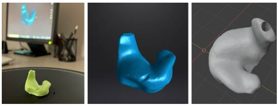 Earmolds Photo: Courtesy of Shining 3D Quality Data Capture Is Key for Successful Reverse Engineeing The use cases above clearly demonstrate the central role of 3D scanning in reverse engineering. It comes as no surprise that the effectiveness and accuracy of data captured by 3D scanning are crucial for a successful reverse engineering process. Yet, the software tools used for processing the data and working with the 3D models are also essential for achieving the desired results in reverse engineering. To understand the importance of good data and adequate software, let’s go over the main steps of reverse engineering with 3D scanning. Step 1. Data acquisition The very first step in any reverse engineering process is data acquisition. Regardless of the method, proper planning and preparation can make the difference between good and poor data. With 3D scanning, this involves selecting the correct device for the job, including the proper configuration (handheld or stationary) and accessories such as turntables, fixtures, and calibration panels. Correct calibration of the device is also vital to acquire quality data. The regions or parts to be digitized usually demand some kind of preparation. Besides a good cleaning, some 3D scanning devices also require the use of markers or even special coatings on reflective surfaces. One should also consider the ambient conditions before starting the digitization process. A controlled environment (e.g. indoors, without direct sunlight, a cleared tabletop, …) is always preferred to reduce noise in the data, but that’s not always possible. All the factors mentioned will contribute to proper data collection, which will in turn determine how quickly and easily the data can be processed next. Step 2. Post-Processing The next step in a reverse engineering process is post-processing the acquired data, or the “point cloud”. Here, the point cloud is processed by software tools – like EinScan software – resulting in a 3D mesh representation of the digitized object. 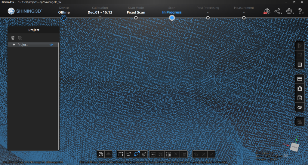 Point Cloud Image In any case, the 3D model in this initial stage usually requires some refinement like removing unwanted captured data, repairing surfaces, and filling gaps per below.  3D mesh data editing, Courtesy of Shining 3D The better the data quality acquired, the less post-processing and repairing will be needed. The post-processing step is also when reference entities are assigned to the 3D model, a procedure that should expedite the next stage of the reverse engineering process. Step 3. CAD Model Generation The final step in a reverse engineering process is to convert the mesh representation of the physical object captured by the 3D scanner into a solid 3D model.  CAD Model from 3D Scan Photo: Courtesy of Shining 3D As accurate as the mesh model can be, it is inadequate for most reverse engineering applications that require additional handling like fixing any physical damage, creating variations, or designing new parts altogether. In this stage, the refined mesh model from the previous step works as an exact reference model for recreating the model using parametric CAD tools. Although in theory any general-purpose CAD program could handle this, specially purposed software geared towards reverse engineering can make the process much easier and yield much better results too. An appropriate CAD software for reverse engineering can also compare the digitized model to the parametric one, allowing users to check for geometrical and dimensional differences. Conclusion Reverse engineering has come a long way and 3D scanning technologies have broadened the range of industrial applications for reverse engineering, benefiting both businesses and consumers. The quality of the captured data is crucial to obtain good results in reverse engineering. The choice of the 3D scanning device, as well as its capabilities and functions, play a central role in the success of the entire process. Read further about how to make sure you choose the right model for your project here. Though often overlooked or underestimated, the software used in the later stages of reverse engineering also bears great importance. Specific built-in tools for the job can make a big difference in a well-executed reverse engineering process. Growshapes the official U.S. distributor of Shining 3D EinScan 3D scanners. We now carry the eviXscan 3D scanner from Evatronix as well!
See the innovators on Growshapes’ social media channels to get the latest expert news on innovation in 3D digitization, then share your thoughts and join the conversation about 3D digital innovation with #digitize3D Solid Edge 2021 brought us powerful performance updates to make our working flow more efficient in the areas of Reverse Engineering as well as Part Modeling, and this year, it moves further, launching the promising and practical next generation design functions, Subdivision Modeling and Convergent Modeling. Let´s take a look at the detailed updates of Solid Edge 2022 and discover its advantages and innovations. Please note:
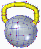
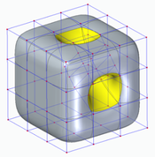
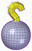
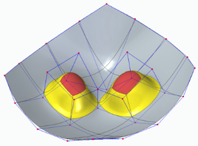
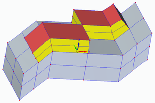
Subdivision Modeling EnhancementsSubdivision Modeling makes it easier to generate a stylized body and control its shape by using a polygonal cage. Solid Edge 2022 introduces new modification functions. 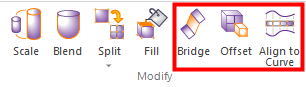 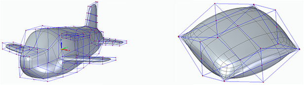 Bridge In the Subdivision Modeling environment, you can use the new "Bridge" command to create a loft-like feature that connects edges or faces selected on a single cage or two separate cages.
Offset Cage Faces Offset allows users to select faces of a cage and offset them along their normal direction. Offset allows users to select faces of a cage and offset them along their normal direction. Offset allows users to select faces of a cage and offset them along their normal direction
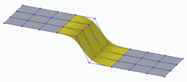
Split with Offset Allows adding local detail to model without having to split the entire model, use the new "Split with Offset" command to add detail to a face by offsetting the new faces inward by a user-defined amount. 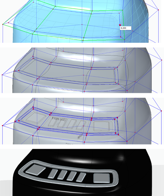 Align to Curve Use the new Align to Curve command to fit the vertices of body cage faces to one or more existing curves or to curves you interactively sketch. You can undo and redo each curve edit until you achieve the desired shape. 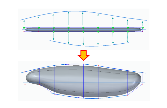 Convergent ModelingSolid Edge now supports mixed mesh modelling (a.k.a Hybrid Convergent modelling). Mesh and Classical faces are in one body, this is extremely helpful when you do assembly reverse engineering and 3D printing. 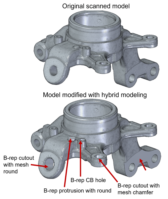 The new "Show Facet Edges" command controls the display of facet edges within a model. When selected, the command displays the facets; when deselected, the facet edges are not displayed. 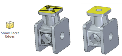 Reference Point Cloud
With all new features, Solid Edge 2022 Shining 3D Edition allows you to do more with your scanned data. It is the practical and efficient solution for engineers, designers and 3D enthusiasts for sure. Growshapes the official U.S. distributor of Shining 3D EinScan 3D scanners. We now carry the eviXscan 3D scanner from Evatronix as well!
See the innovators on Growshapes’ social media channels to get the latest expert news on innovation in 3D digitization, then share your thoughts and join the conversation about 3D digital innovation with #digitize3D Challenge: Finding replacement parts for a classic car
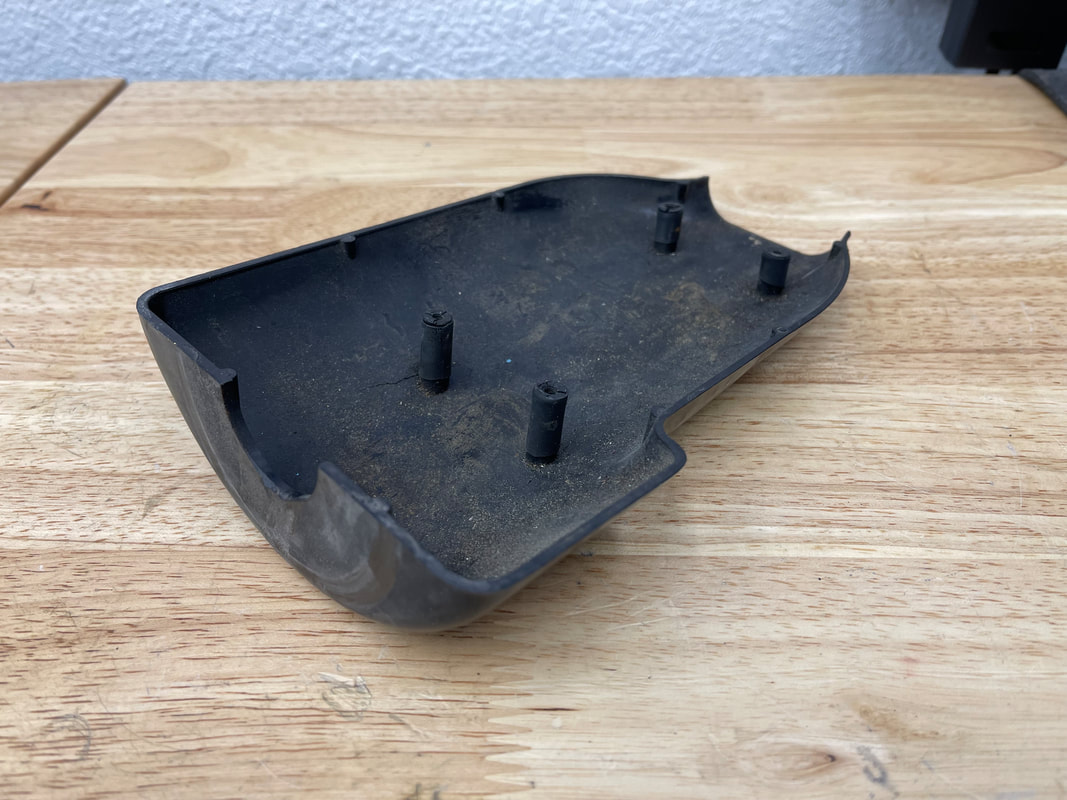
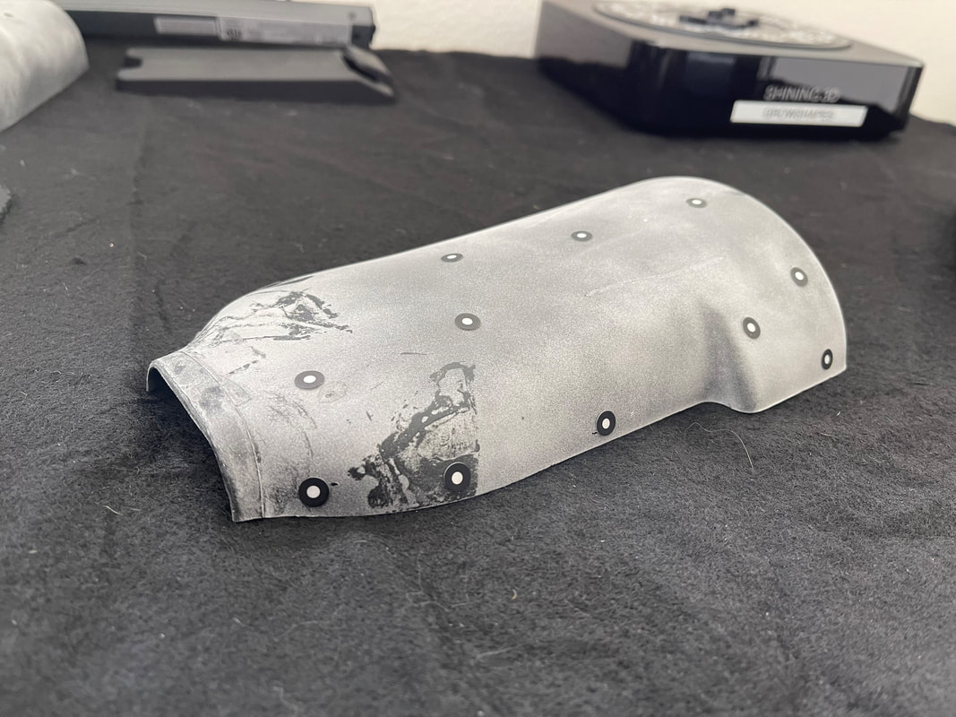
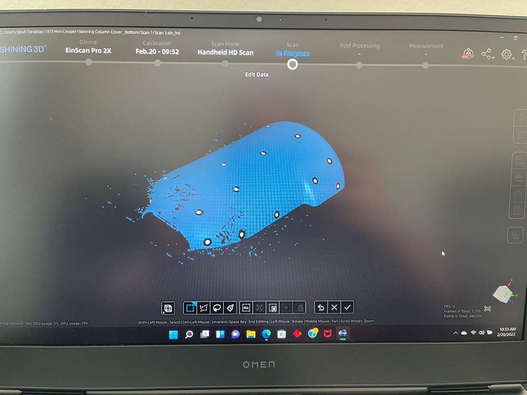
Solution: EinScan Pro 2X fills the gap John, also being a talented engineer and with his deep knowledge of 3D printing technology, he decided to reverse engineer these Mini Cooper steering column covers and 3D print new replacement parts. Rather than measuring the parts with a caliper and designing in CAD from scratch, John decided to 3D scan the plastic steering column covers to generate a 3D digital surface model to get accurate measurements of the parts with the EinScan Pro 2X 3D scanner
 The EinScan Pro 2X 3D scanner with the Industrial Kit enabled John to put the object on the turntable and within an hour or so, get a workable 3D mesh. Multiple scans were automatically fused together to create a watertight 360-degree digital surface mesh that was then imported into the Solid Edge Shining 3D Edition reverse engineering software. The surface mesh files were leveraged to build a solid model, make design improvements, and then be further process for 3D printing. Results: Capturing details enabled precise CAD file creation for 3D printing
“By using the 3D scanner, I was able to focus on creating the CAD file suitable for 3D printing without having to wrestle with measurements and generating a CAD file from scratch.” - John Buffington. Also importatnt to note is to understand copyright laws in the US. Reverse engineering is legal but if you are going to reproduce and profit, you should get in touch with a patent lawyer. With an old part like above, it's beyond the copyright Growshapes the official U.S. distributor of Shining 3D EinScan 3D scanners. We now carry the eviXscan 3D scanner from Evatronix as well!
See the innovators on Growshapes’ social media channels to get the latest expert news on innovation in 3D digitization, then share your thoughts and join the conversation about 3D digital innovation with #digitize3D 3D scanner is a data-acquiring device that captures the surface model of a physical object in a digital polygonal model. The types of output data format that 3D scanners can generate maybe confusing. What is an ASC file? Which export formats does my CAD software import for rapid prototyping? What is the best practice for saving scans? Which file format is the best choice for 3D printing? In this post, we will discuss all file types that involve Einscan software. The type of file you require depends on what you are going to do after the scanning process. There are a total of 6 types of output data formats (ASC, p3, STL, PLY, OBJ, 3MF) that you can export from EinScan software during data capture and generating mesh which are polygon models. We will explain the differences among these 6 file types in this blog. Point Cloud Data Format When you have finished your scan and are ready to convert your raw scan data to point cloud data, you can click on the save button to save the point cloud data as an ASC file and the marker position as p3 format when markers are detected. ASC file contains the position information of each point in the point cloud. This file type can be opened in most scan data processing software and metrology software like Meshmixer, GOM Inspect, and Geomagic Essentials. The P3 file is for marker reuse purposes in EinScan software. For a large object scan, the user can scan all markers only first and save the marker frame as a p3 file. Later the object can be scanned part by part in a separate project using the same p3 file as a reference which improves the accuracy and will require no alignment between each project. 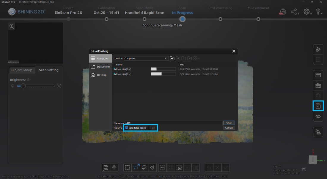 With Fix scan mode number of scans will be saved as separate files, while for handheld scans the full point cloud will be saved as one file. Meshed Data File Format After the data is meshed, more saving options will be available. ASC file is still available while the mesh can be saved as STL, PLY, OBJ, or 3MF files. STL file format is the most common mesh file format. It only contains the position and normal directions of all triangles in the mesh. This polygon file format can be opened by mesh editing software and many CAD software like Solid Edge or Solidworks for reverse engineering. PLY and OBJ file formats contain mesh texture information, including color information, in addition to the STL file. Users can export these data types for digital documentation and online model display. 3MF file is the 3D printing format published by the 3MF Consortium. This format includes information about materials, colors, and other information that cannot be represented in the STL format. Windows system and other CAD software packages can open this mesh format. 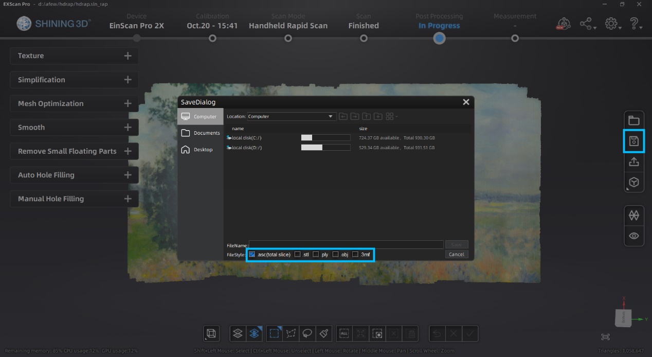 Post Processing Data EinScan software provides basic functions for mesh editing in Post Processing and Measurement sections. Usually, users use these functions right after meshing data. However, external mesh data can also be imported into the EinScan software for editing. The EinScan software supports STL, OBJ, and PLY formats for post-processing and measurement. 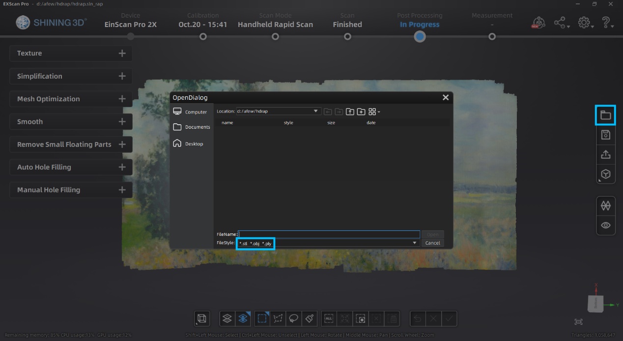
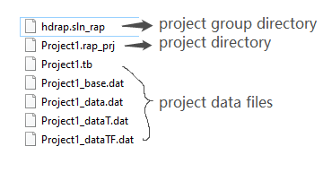
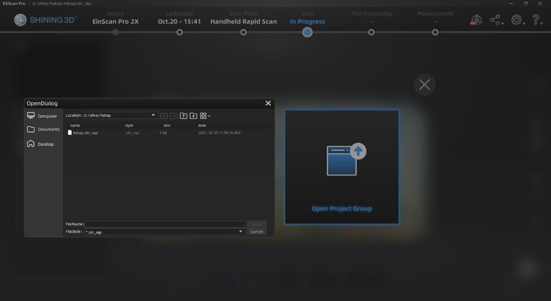
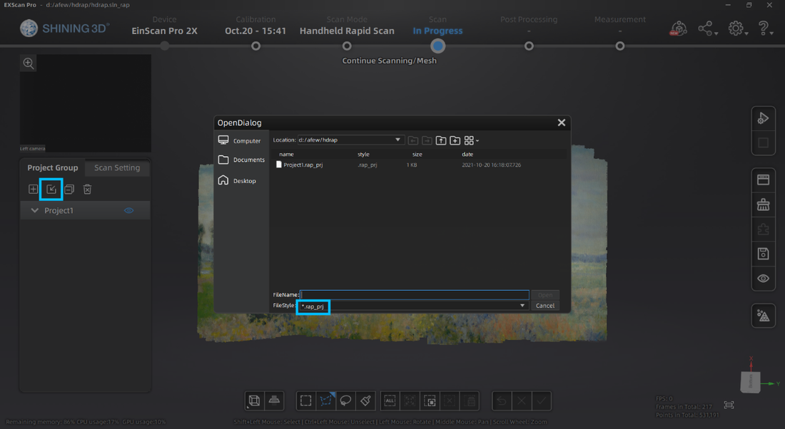
The project group folder contains different kinds of files. The project group directory links all projects in the group. The project directory links all data files belonging to this project and the rest are project data files. When moving the project group, the user needs to move all the folders in the project group. When opening the project, the user needs to locate the folder where the project group was saved and open the corresponding directory files.The project group folder contains different file formats. The project group directory links all projects in the group. The project directory links all data files belonging to this project and the rest are project data files. When moving the project group, the user needs to move all the folders in the project group. When opening the project, the user must locate the folder where the project group was saved and open the corresponding directory files.
So that's it! You have 6 output formats to choose from and all the required scans for your saved project will be in a project group folder. Remember, the file size for each project is large, so make sure you secure a space on your PC where you can save the files. Growshapes the official U.S. distributor of Shining 3D EinScan 3D scanners. We now carry the eviXscan 3D scanner from Evatronix as well!
See the innovators on Growshapes’ social media channels to get the latest expert news on innovation in 3D digitization, then share your thoughts and join the conversation about 3D digital innovation with #digitize3D  3D Printed Valves. Photo courtesy of dezeen. Recently the media picked up a story about how 3D printing saved the day to produce valves for an intensive care unit in Italy to treat COVID-19 patients. The Italian startup company reverse engineered, and 3D printed these valves that are key components of Venturi oxygen masks that are connected to ventilators. When you read the details however, you realize they jumped various legal hurdles to do this - the valve is protected by copyright and patents with its blueprint not released but in an emergency case such as this one, the hospital seemed to have allowed them to reverse engineer the valve and 3D print them. The CEO of the company that 3D printed the valves is now is explaining what his intentions were on his Facebook post and LinkedIn video (in Italian). When emergencies of such enormous scale occur as is happening right in front of our eyes, you just want to help if you have the capability and technology to solve the problem quickly. But regulations exist to ensure safety and durability thus everybody in the 3D printing industry is doing a thoughtful balancing act. It is not clear if they used a 3D scanner or just used calipers to do the reverse engineering but 3D scanners can play a key role in enabling accurate and quick reverse engineering of physical objects. Using 3D scanning technology, you can capture the surface dimensions of complex physical objects accurately and quickly especially with the structured light 3D scanners, then then reverse engineer with various CAD software such as Geomagic and Solid Edge which comes bundled with EinScan Pro 2X & 2X Plus to create a blueprint that can be 3D printed. Have a look at how you can reverse engineer products that are missing a blueprint by using 3D scanners. https://www.growshapes.com/einscan-pro-2x-3d-scanner-series-bundle.html Growshapes is an HP Silver Partner of HP 3D scanning solutions and the official U.S. distributor of Shining 3D EinScan 3D scanners. We are now carrying the eviXscan 3D scanner from Evatronix too!
See the innovators on Growshapes’ social media channels to get the latest expert news on innovation in 3D digitization, then share your thoughts and join the conversation about 3D digital innovation with #digitize3D.  Starting today until December 20, 2019 you will receive 1 free Color Pack accessory when you buy the complete EinScan Reverse Engineering Design (RED) Bundle for the EinScan Pro 2X or EinScan Pro 2X Plus. SHINING 3D’s RED bundle is the premier solution for scan to 3D design workflows as it features both Geomagic Essentials by 3D systems and Solid Edge SHINING 3D Edition by Siemens PLM software. Complete reverse engineering has never been easier than with the EinScan RED bundle. Geomagic Essentials is the ideal solution for scan to print and downstream reverse engineering applications as it extracts all the necessary elements of a scanned part for immediate use in CAD software programs. This functionality allows for an easy transition into Solid Edge SHINING 3D Edition. With the convenient and powerful CAD tools provided by Solid Edge, you can complete reverse engineering, generative design, and simulation to achieve your creative ideas. Read more here. The complete RED Bundle with this special promotion includes:
There has never been a more complete package for 3D scan to design workflows! Growshapes is an HP Silver Partner of HP 3D scanning solutions and the official U.S. distributor of Open Technologies 3D Scanners and Shining 3D EinScan 3D scanners.
See the innovators on Growshapes’ social media channels to get the latest expert news on innovation in 3D digitization, then share your thoughts and join the conversation about 3D digital innovation with #digitize3D |
GrowshapesProvider of leading edge 3D scanning products and services. We see 3D! Archives
July 2024
Categories
All
|
||||||||||||||||||||||||||||||||||


 RSS Feed
|
Vertical Divider
GROWSHAPESStay connected |
Menu |


|
©2024 Growshapes LLC. All rights reserved.