
|
Alignment is an important step for 3D scanning to ensure the 360 degree digital surface model generated by the 3D scanner accuractly replicates the physical object. With Shining 3D scanners, there are several alignment methods that can be deployed, depending on the shape of the target object. Let's go through them one by one.
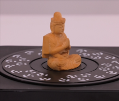
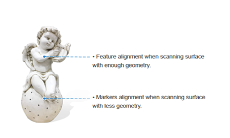
2. Feature Alignment
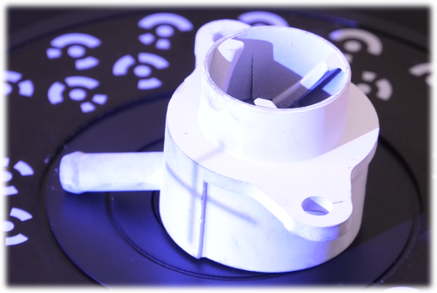
3. Markers Alignment
4. Texture Alignment
5. Hybrid Alignment
Also important to remember is when you are 3D scanning a large object on a tripod without a turntable, you need to ensure there is at least a 30% overlap from one scan to the next to ensure alignment. 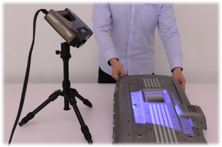 So that's it. Not as difficult as you thought, right? Growshapes the official U.S. distributor of Shining 3D EinScan 3D scanners. We now carry the eviXscan 3D scanner from Evatronix as well!
See the innovators on Growshapes’ social media channels to get the latest expert news on innovation in 3D digitization, then share your thoughts and join the conversation about 3D digital innovation with #digitize3D
0 Comments
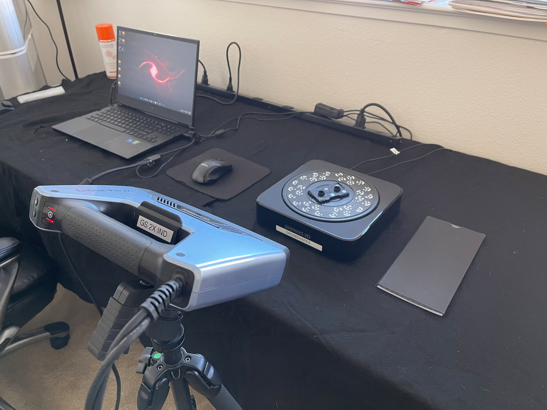
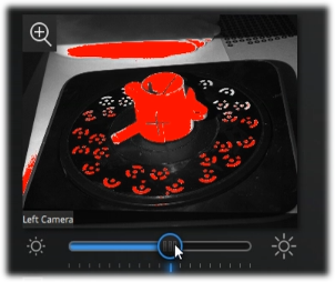
Structured light 3D scanners use the projector light to project structured light patterns onto your target object, while the cameras capture the change in the structured light patterns and the 3D scan software generates the 360 degree digital surface model of your target physcial object. Therefore, for any structured light 3D scanner, adjusting the 3D scanner projector brightness level is very important. This enables the 3D scanner to project the sturctured light pattern adequately to capture the surface dimensions of the target object. See below for guidance. 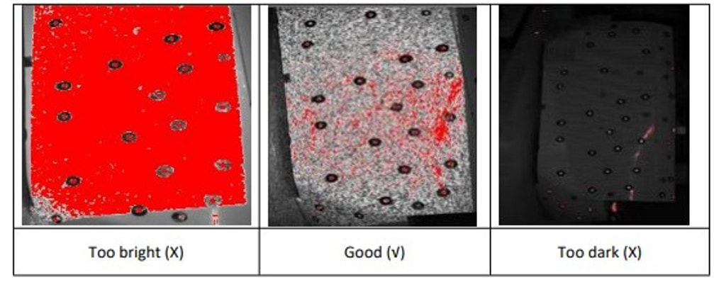 It is important to adjust your distance between the 3D scanner and the target object as well as the brightness.
Make sure you get the hang of the correct brightness as well as the distance between the object and the 3D scanner, so your 3D scanning process will proceed smoothly! Growshapes the official U.S. distributor of Shining 3D EinScan 3D scanners. We now carry the eviXscan 3D scanner from Evatronix as well!
See the innovators on Growshapes’ social media channels to get the latest expert news on innovation in 3D digitization, then share your thoughts and join the conversation about 3D digital innovation with #digitize3D Solid Edge 2021 brought us powerful performance updates to make our working flow more efficient in the areas of Reverse Engineering as well as Part Modeling, and this year, it moves further, launching the promising and practical next generation design functions, Subdivision Modeling and Convergent Modeling. Let´s take a look at the detailed updates of Solid Edge 2022 and discover its advantages and innovations. Please note:
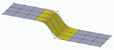
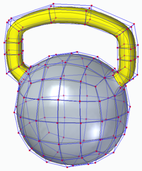
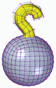
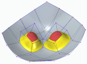
Subdivision Modeling EnhancementsSubdivision Modeling makes it easier to generate a stylized body and control its shape by using a polygonal cage. Solid Edge 2022 introduces new modification functions. 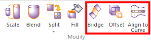 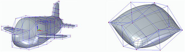 Bridge In the Subdivision Modeling environment, you can use the new "Bridge" command to create a loft-like feature that connects edges or faces selected on a single cage or two separate cages.
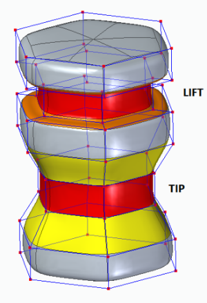
Offset Cage Faces Offset allows users to select faces of a cage and offset them along their normal direction. Offset allows users to select faces of a cage and offset them along their normal direction. Offset allows users to select faces of a cage and offset them along their normal direction
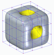
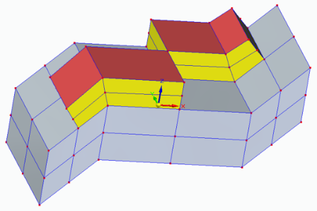
Split with Offset Allows adding local detail to model without having to split the entire model, use the new "Split with Offset" command to add detail to a face by offsetting the new faces inward by a user-defined amount. 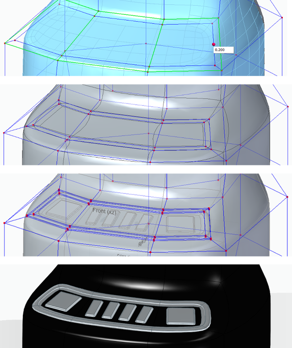 Align to Curve Use the new Align to Curve command to fit the vertices of body cage faces to one or more existing curves or to curves you interactively sketch. You can undo and redo each curve edit until you achieve the desired shape. 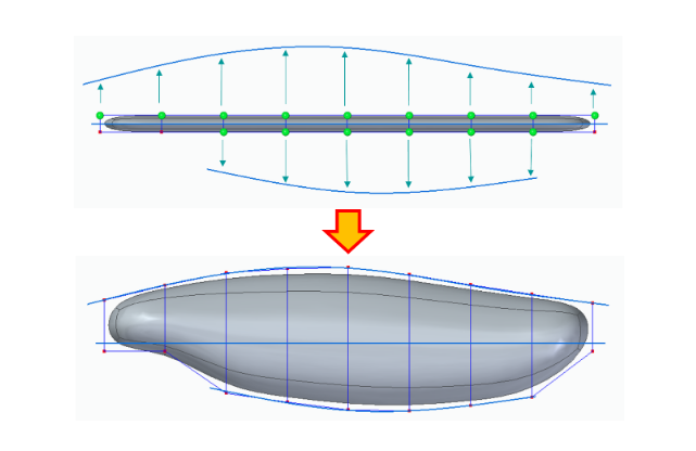 Convergent ModelingSolid Edge now supports mixed mesh modelling (a.k.a Hybrid Convergent modelling). Mesh and Classical faces are in one body, this is extremely helpful when you do assembly reverse engineering and 3D printing. 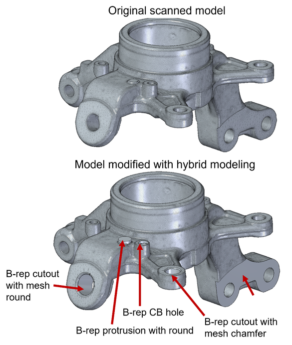 The new "Show Facet Edges" command controls the display of facet edges within a model. When selected, the command displays the facets; when deselected, the facet edges are not displayed. 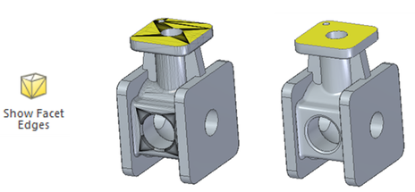 Reference Point Cloud
With all new features, Solid Edge 2022 Shining 3D Edition allows you to do more with your scanned data. It is the practical and efficient solution for engineers, designers and 3D enthusiasts for sure. Growshapes the official U.S. distributor of Shining 3D EinScan 3D scanners. We now carry the eviXscan 3D scanner from Evatronix as well!
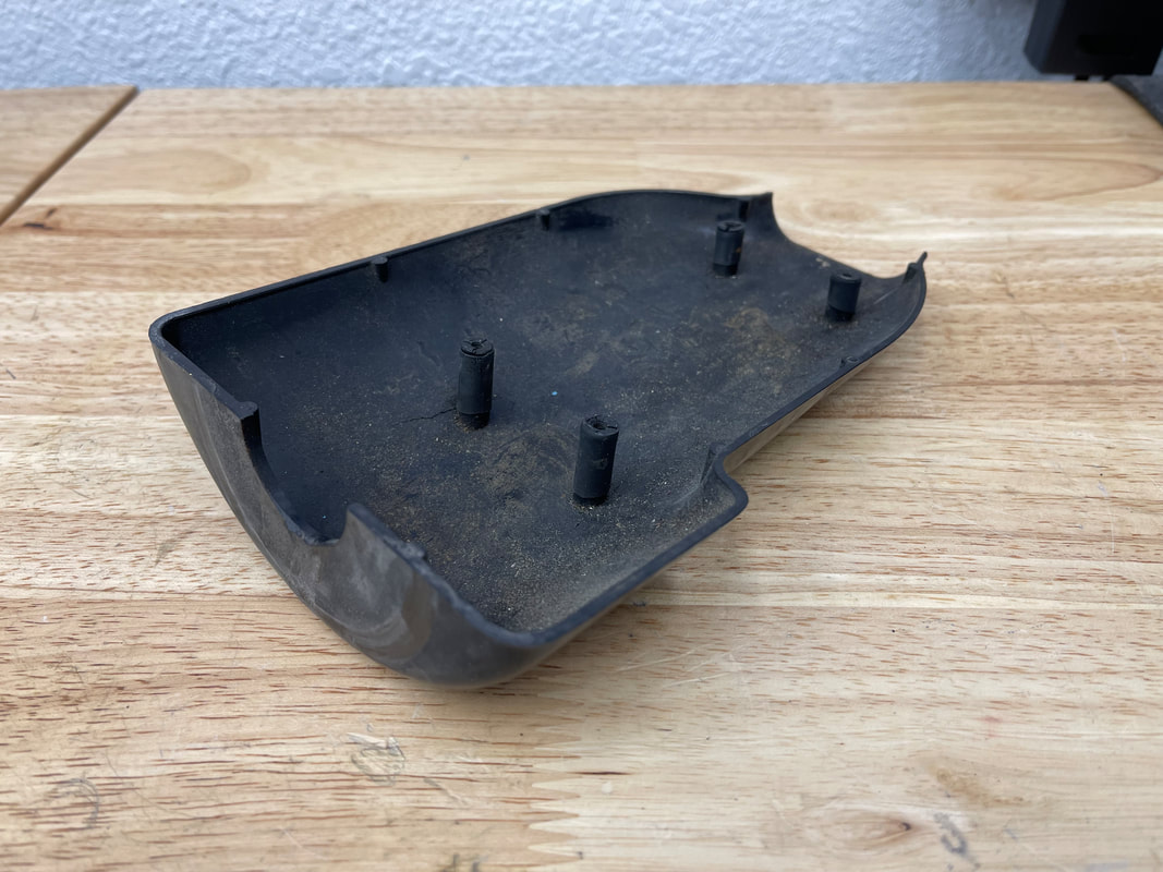
See the innovators on Growshapes’ social media channels to get the latest expert news on innovation in 3D digitization, then share your thoughts and join the conversation about 3D digital innovation with #digitize3D Challenge: Finding replacement parts for a classic car
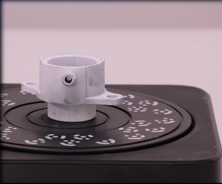
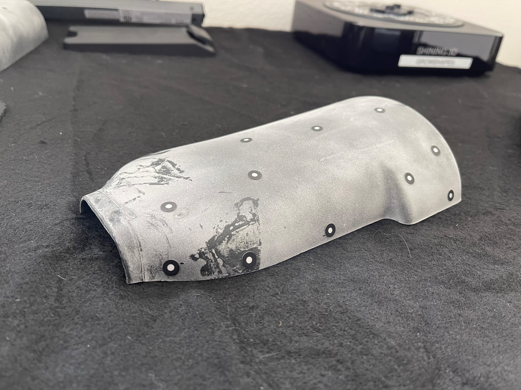
Solution: EinScan Pro 2X fills the gap John, also being a talented engineer and with his deep knowledge of 3D printing technology, he decided to reverse engineer these Mini Cooper steering column covers and 3D print new replacement parts. Rather than measuring the parts with a caliper and designing in CAD from scratch, John decided to 3D scan the plastic steering column covers to generate a 3D digital surface model to get accurate measurements of the parts with the EinScan Pro 2X 3D scanner
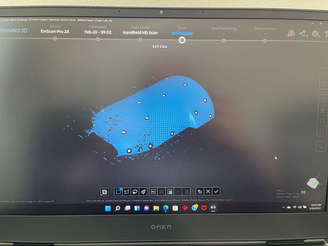
 The EinScan Pro 2X 3D scanner with the Industrial Kit enabled John to put the object on the turntable and within an hour or so, get a workable 3D mesh. Multiple scans were automatically fused together to create a watertight 360-degree digital surface mesh that was then imported into the Solid Edge Shining 3D Edition reverse engineering software. The surface mesh files were leveraged to build a solid model, make design improvements, and then be further process for 3D printing. Results: Capturing details enabled precise CAD file creation for 3D printing
“By using the 3D scanner, I was able to focus on creating the CAD file suitable for 3D printing without having to wrestle with measurements and generating a CAD file from scratch.” - John Buffington. Also importatnt to note is to understand copyright laws in the US. Reverse engineering is legal but if you are going to reproduce and profit, you should get in touch with a patent lawyer. With an old part like above, it's beyond the copyright Growshapes the official U.S. distributor of Shining 3D EinScan 3D scanners. We now carry the eviXscan 3D scanner from Evatronix as well!
See the innovators on Growshapes’ social media channels to get the latest expert news on innovation in 3D digitization, then share your thoughts and join the conversation about 3D digital innovation with #digitize3D 3D scanner is a data-acquiring device that captures the surface model of a physical object in a digital polygonal model. The types of output data format that 3D scanners can generate maybe confusing. What is an ASC file? Which export formats does my CAD software import for rapid prototyping? What is the best practice for saving scans? Which file format is the best choice for 3D printing? In this post, we will discuss all file types that involve Einscan software. The type of file you require depends on what you are going to do after the scanning process. There are a total of 6 types of output data formats (ASC, p3, STL, PLY, OBJ, 3MF) that you can export from EinScan software during data capture and generating mesh which are polygon models. We will explain the differences among these 6 file types in this blog. Point Cloud Data Format When you have finished your scan and are ready to convert your raw scan data to point cloud data, you can click on the save button to save the point cloud data as an ASC file and the marker position as p3 format when markers are detected. ASC file contains the position information of each point in the point cloud. This file type can be opened in most scan data processing software and metrology software like Meshmixer, GOM Inspect, and Geomagic Essentials. The P3 file is for marker reuse purposes in EinScan software. For a large object scan, the user can scan all markers only first and save the marker frame as a p3 file. Later the object can be scanned part by part in a separate project using the same p3 file as a reference which improves the accuracy and will require no alignment between each project. 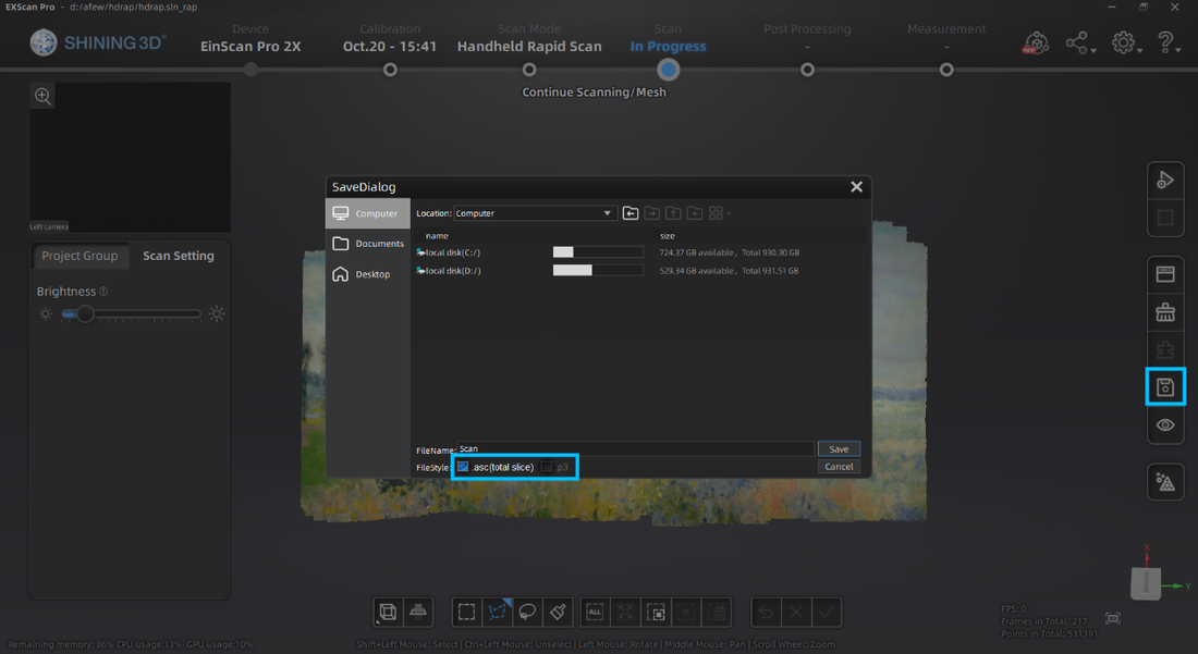 With Fix scan mode number of scans will be saved as separate files, while for handheld scans the full point cloud will be saved as one file. Meshed Data File Format After the data is meshed, more saving options will be available. ASC file is still available while the mesh can be saved as STL, PLY, OBJ, or 3MF files. STL file format is the most common mesh file format. It only contains the position and normal directions of all triangles in the mesh. This polygon file format can be opened by mesh editing software and many CAD software like Solid Edge or Solidworks for reverse engineering. PLY and OBJ file formats contain mesh texture information, including color information, in addition to the STL file. Users can export these data types for digital documentation and online model display. 3MF file is the 3D printing format published by the 3MF Consortium. This format includes information about materials, colors, and other information that cannot be represented in the STL format. Windows system and other CAD software packages can open this mesh format. 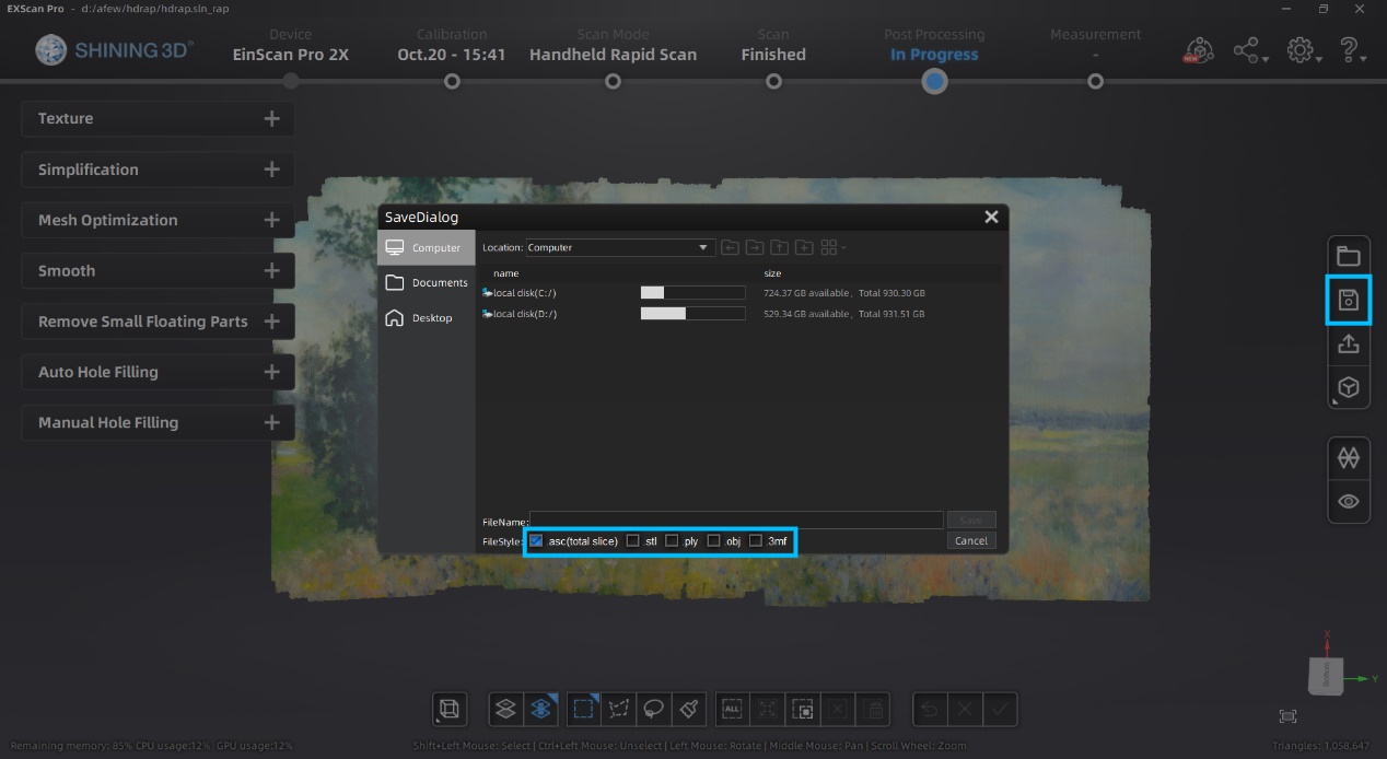 Post Processing Data EinScan software provides basic functions for mesh editing in Post Processing and Measurement sections. Usually, users use these functions right after meshing data. However, external mesh data can also be imported into the EinScan software for editing. The EinScan software supports STL, OBJ, and PLY formats for post-processing and measurement. 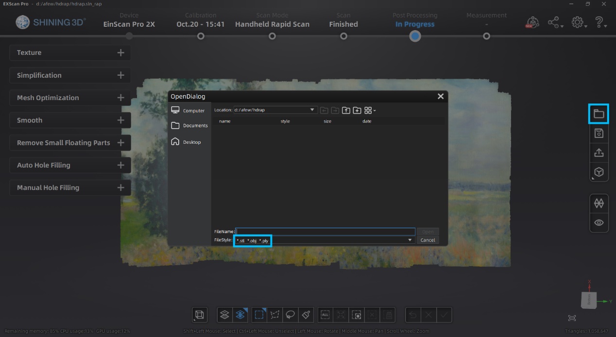
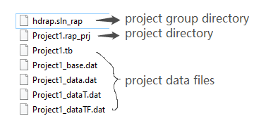
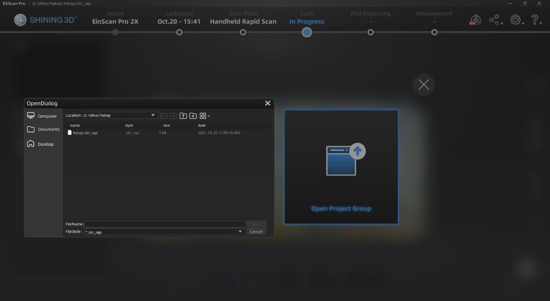
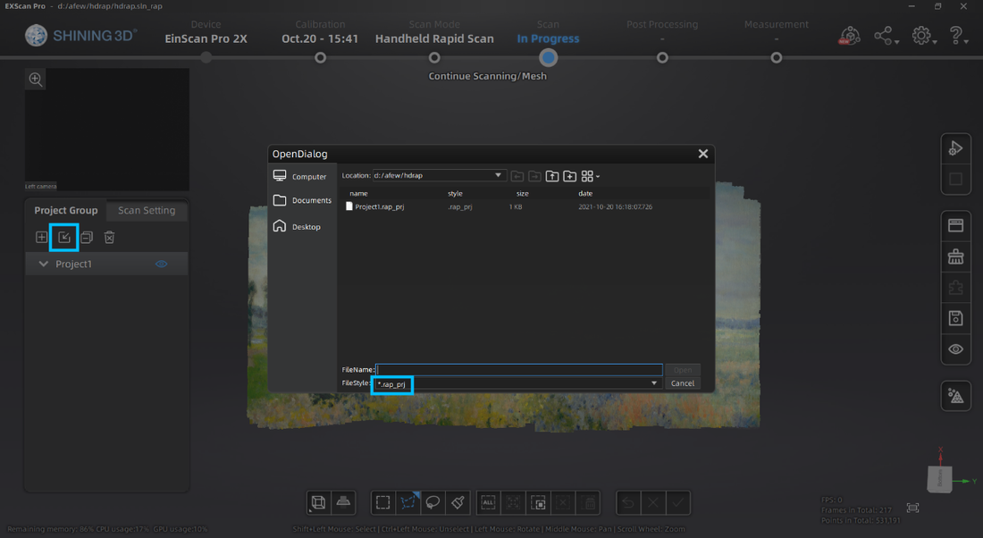
The project group folder contains different kinds of files. The project group directory links all projects in the group. The project directory links all data files belonging to this project and the rest are project data files. When moving the project group, the user needs to move all the folders in the project group. When opening the project, the user needs to locate the folder where the project group was saved and open the corresponding directory files.The project group folder contains different file formats. The project group directory links all projects in the group. The project directory links all data files belonging to this project and the rest are project data files. When moving the project group, the user needs to move all the folders in the project group. When opening the project, the user must locate the folder where the project group was saved and open the corresponding directory files.
So that's it! You have 6 output formats to choose from and all the required scans for your saved project will be in a project group folder. Remember, the file size for each project is large, so make sure you secure a space on your PC where you can save the files. Growshapes the official U.S. distributor of Shining 3D EinScan 3D scanners. We now carry the eviXscan 3D scanner from Evatronix as well!
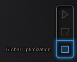
See the innovators on Growshapes’ social media channels to get the latest expert news on innovation in 3D digitization, then share your thoughts and join the conversation about 3D digital innovation with #digitize3D The new version of the ExScan software ExScan 3.7 compatible with EinScan Pro 2X/2X Plus/2X 2020/Pro HD is now available. It is updated enhanced digital toolkits and adds exciting new features that will enable you to speed up your scan editing & mesh optimization as well as empower you to do more things efficiently! 1. Enhanced Point Cloud Editing Point cloud editing now has become easier with enhanced selection of editing tools including Rectangular and polygon selection tool, the “Cutting Plane” function and the “Connected Domain” selection function.  2. More Tools to Optimize Your Mesh The Mesh Optimization function has been redesigned to create clean meshes fast and easily. The mesh optimization has now a broader range of selection tools to enable you to edit like a pro. 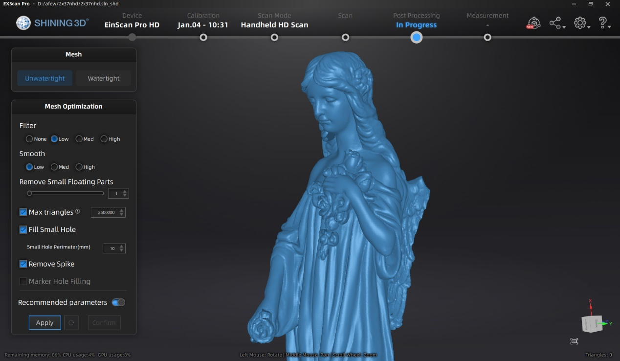 3. New File Manager The file manager has been redesigned to access your files more efficiently. 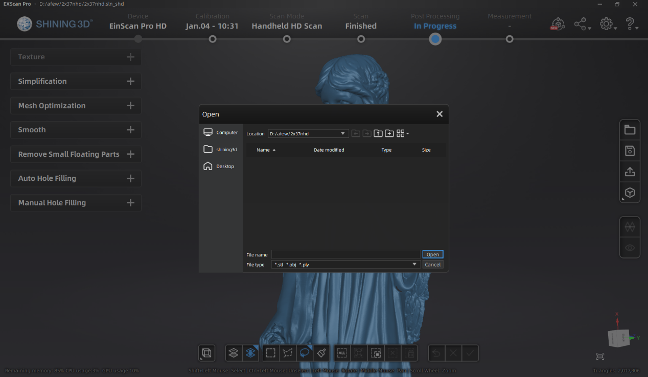 4. Global Optimization as a separate step
5. User Account Center In order to provide users a platform for scanner management and learn about all things EinScan, the all new User Account Center has been added. By downloading ExScan V3.7, you will get a free user account to get the software started. Offline activation is accessible without contacting support person now as well. Please make sure your device is connected for log in and activation. Finally, please make sure your NVIDIA graphics card has the compute capability of 5.0 or above by checking your graphics card capability from here: https://developer.nvidia.com/cuda-gpus#compute Growshapes the official U.S. distributor of Shining 3D EinScan 3D scanners. We now carry the eviXscan 3D scanner from Evatronix as well!
See the innovators on Growshapes’ social media channels to get the latest expert news on innovation in 3D digitization, then share your thoughts and join the conversation about 3D digital innovation with #digitize3D Geomagic Essentials brings you the tools to use the CAD system as a part of your scan-based modeling workflow. Converting 3D scans to CAD has never been easier. Geomagic Essentials is the bridge software that extracts all the necessary elements of a scanned part for immediate use in your CAD software. Bridging the gap between 3D scanning and CAD, Geomagic Essentials has become an indispensable tool for the SHINING 3D user community. Geomagic Essentials V2 - what's new?As our goal as your trusted 3D scanning provider is to improve your daily working routines and adapt our products and solutions to your real needs, we are happy to introduce to you some of the main features of Geomagic Essentials V2, which will sustainably and effectively improve the way you work! 1. Trim Mesh with Plane/Curve Several options are available that allow you to trim (remove) polygons from an object. These options can all be accessed via the Trim button. 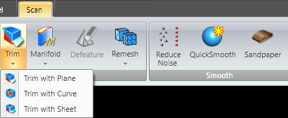 Instruction video: https://s3.amazonaws.com/dl.3dsystems.com/binaries/support/downloads/videochannel/Studio/TrimPolygons/TrimPolygons.mp4 2. Flipping Normals The Flip Normals command reverses the normal direction of a polygon mesh. In other words, the front and back sides of the entire mesh are flipped. 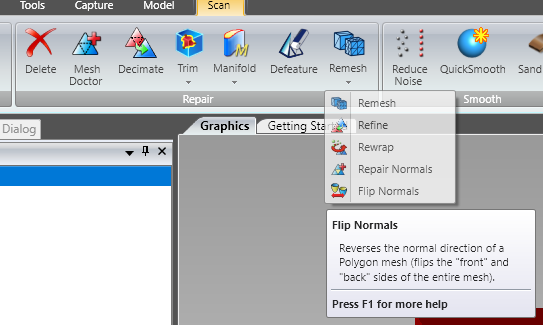 3. Shell/Thicken Mesh You can define the level of thickness for your polygon model by duplicating and offsetting a mesh in either a single direction (shell) or in two directions (thicken). 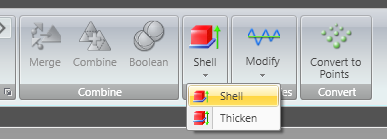 Instruction video: https://s3.amazonaws.com/dl.3dsystems.com/binaries/support/downloads/videochannel/Studio/ShellandThicken/ShellandThickenPolygons.mp4 4. Predefined views in the right-click menu 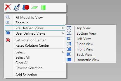 This update is completely FREE for all of our current users! Sounds exciting!? There´s so much more to look forward to! Keep your eyes peeled for the announcement of a new EinScan software update! We are working on some great new features for you, including importing your scan data into Geomagic Essentials V2 with one click! Important note: The current software only supports one click import to the initial version of Geomagic Essentials. After upgrading to the new version, you need to save the data first and then open Geomagic Essentials V2 to edit the scan data. We are working on the integration of EinScan software with Geomagic Essentials V2 to the next update of ExScan. Stay tuned. Growshapes the official U.S. distributor of Shining 3D EinScan 3D scanners. We now carry the eviXscan 3D scanner from Evatronix as well!
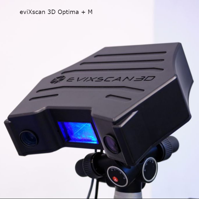
See the innovators on Growshapes’ social media channels to get the latest expert news on innovation in 3D digitization, then share your thoughts and join the conversation about 3D digital innovation with #digitize3D EinScan SE, EinScan Pro HD, EinScan H & EinScan HX make the All3DP "Best Professional 3D Scanner 2021" list, while eviXscan's latest 3D scanner Optima + M makes the "Best Industrial 3D Scanner 2021" list! "Selecting the right 3D scanner is no simple task. There’s a lot to keep in mind, but the main place to start is to define what you’re going to scan. One 3D scanner may be the best for small stationary objects, but may prove unsuitable for scanning people’s faces. With many scanners there’s a trade off between fine detail and speed, although some have settings for both." - All3DP.pro This is why Growshapes exists - to help you through the myriad of choices available in the 3D scanning world and the different requirements each customer has. We hand-pick what we think would be best for our customers based on the hardware & software quality, support quality and price. We guide you through how to choose the best handheld 3D scanner model from EinScan to achieve your objectives to help you make the right choice. EinScan 3D Scanners on the All3DP listeviXscan 3D Scanner on the All3DP list
Read the full list from All3DP here. Growshapes the official U.S. distributor of Shining 3D EinScan 3D scanners. We now carry the eviXscan 3D scanner from Evatronix as well!
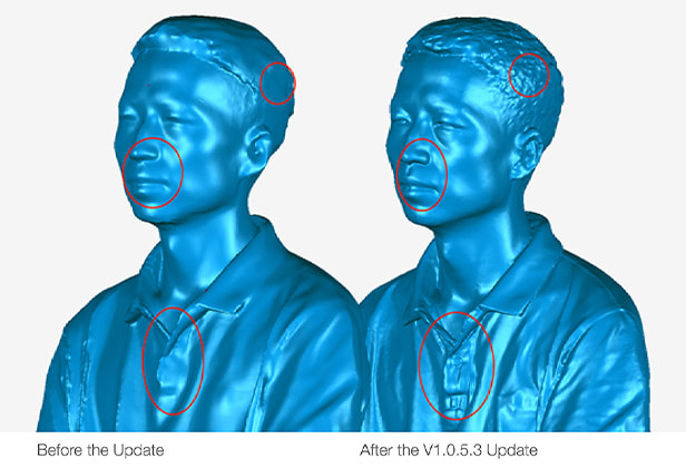
See the innovators on Growshapes’ social media channels to get the latest expert news on innovation in 3D digitization, then share your thoughts and join the conversation about 3D digital innovation with #digitize3D EinScan H users, download the latest software version V1.0.5.3 Exscan H that enables the capture of fine details when using Infrared Scanning, Face Scan Mode. With the newly developed algorithm, the software can capture more details around the face with invisible Infrared light. Check out the details below.
EinScan H is also useful in making 3D digital replicas of ancient artifacts which may be sensitive to white light. 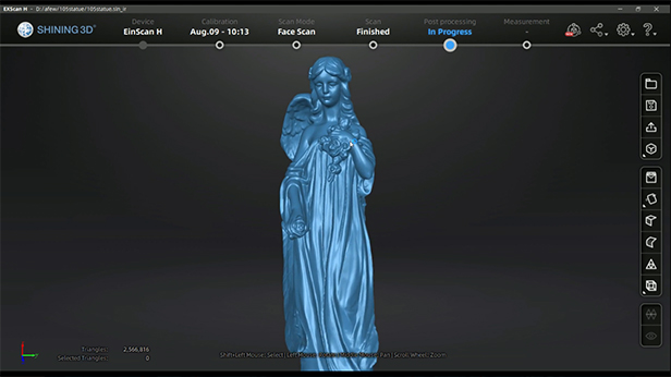 The combination of great hardware and software truly makes a difference in how much detail can be captured with 3D scanning technology. The team behind EinScan 3D scanners continues to innovate pushing frequent software updates and develping new software algorithms, so make sure you have the latest software to get the benefits of all the new features! Growshapes is an HP Silver Partner of HP 3D scanning solutions and the official U.S. distributor of Shining 3D EinScan 3D scanners. We are now carry the eviXscan 3D scanner from Evatronix as well!
See the innovators on Growshapes’ social media channels to get the latest expert news on innovation in 3D digitization, then share your thoughts and join the conversation about 3D digital innovation with #digitize3D. With the latest EinScan HX v1.2.0.2 software update, a new mesh editing function has been added. Unlike other post-process function which only do a single operation, the new “Mesh Optimization” feature in EinScan HX software allows you to do both smooth and sharpen concurrently which will eliminate surface noise while keeping sharp details. You can choose the optimization intensity from 0 to 100%. You can do multiple iterations if not satisfied with current outcomes. This function performs well when the original data has a small point distance. For example, here’s a part of the tires scanned with 0.2mm resolution. 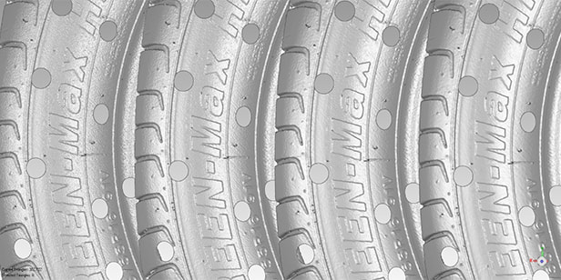 From left to right are original data / 20% / 50%/ 100% optimization. 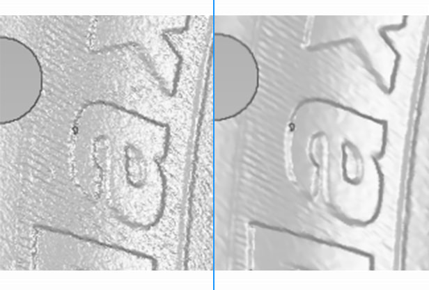 You can see that surface noise was well removed under 100% optimization, but the edges of the letters are still sharp. However, on a large point distance model, the details are already blurred. Using high optimization intensity will cause detail loss. Here is an example. 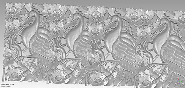 Same intensity from left to right while the resolution is 1mm. You can tell that the details on feathers are hard to tell with 100% optimization. All in all, we suggest using high intensity optimization (100%) for high resolution and low intensity optimization (20%) for low resolution. Play around with this feature to fine tune the generate the desired outcome. And if the resolution is beyond 1mm, we do not recommend applying mesh optimization. Hope this function can help you get a good scan result easier! Growshapes is an HP Silver Partner of HP 3D scanning solutions and the official U.S. distributor of Shining 3D EinScan 3D scanners. We are now carry the eviXscan 3D scanner from Evatronix as well!
See the innovators on Growshapes’ social media channels to get the latest expert news on innovation in 3D digitization, then share your thoughts and join the conversation about 3D digital innovation with #digitize3D. |
growshapesProvider of leading edge 3D scanning products and services. We see 3D! Archives
March 2024
Categories
All
|


 RSS Feed
|
Vertical Divider
GROWSHAPES963 Topsy Ln STE 306 PMB 245, Carson City, NV 89705
+1 408-667-6877 Email: info@growshapes.com Stay connected |
Menu |


|